Fan unit

A fan and fan wheel technology, applied in the field of fans that can increase the air intake, can solve the problems of not being large enough, unable to effectively display the heat dissipation effect, and the area of ​​the air inlet being limited.

Inactive Publication Date: 2007-05-30
ASIA VITAL COMPONENTS SHENZHEN CO LTD
View PDF0 Cites 0 Cited by
  • Summary
  • Abstract
  • Description
  • Claims
  • Application Information

AI Technical Summary

Problems solved by technology

[0006] The described embodiment has its problems in operation. As shown in the figure of this case, the outward extension of the inner peripheral wall does not exceed its screw hole, and the outward extension is only limited to the Exceeding the range of the screw hole, the area of ​​the air inlet is limited and not large enough, and the heat dissipation effect cannot be effectively demonstrated

Method used


Image

  • Fan unit
  • Fan unit
  • Fan unit

Examples


Embodiment Construction

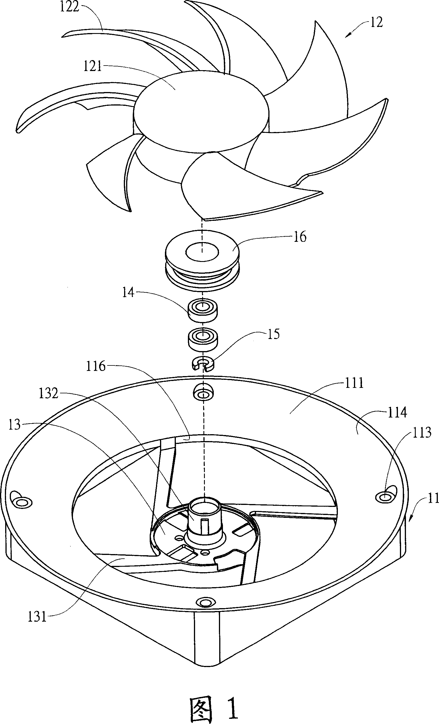
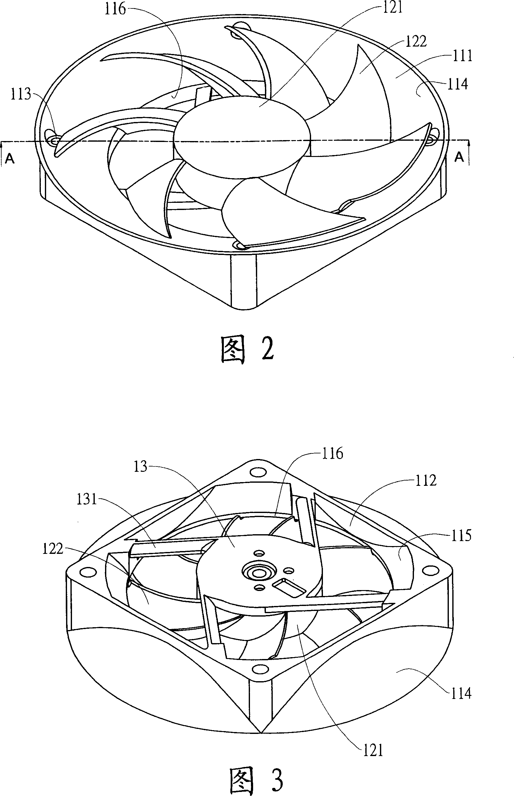
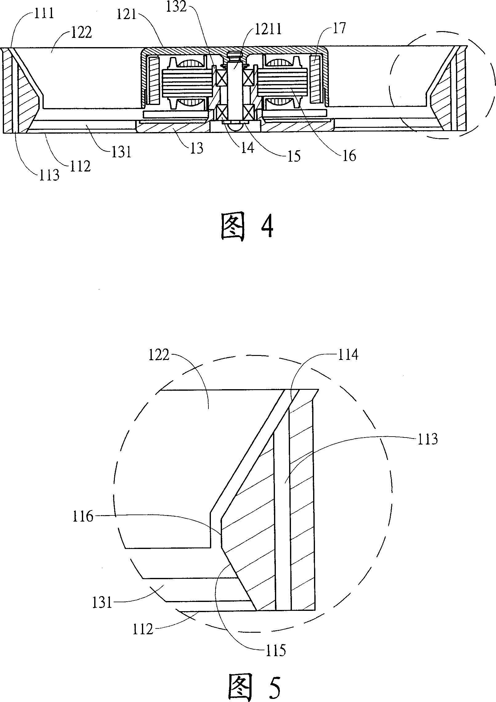
[0022] The present invention provides a fan unit, the accompanying drawings are preferred embodiments of the present invention, please refer to Figure 1 to Figure 4 shows the first preferred embodiment of the present invention, which at least includes a frame 11 and a fan wheel 12, wherein the frame body 11 has a flow channel through the frame body 11, and the flow channel forms a first through hole 111 and a second through hole 112 on both sides of the frame body 11, and a The through hole 113 is provided for the fixing assembly to pass through, and the inner side of the frame body 11 is formed at the first through hole 111, which is inclined from the outside of the frame body 11 to the inside of the frame body 11 and radially outward and extends at least beyond the frame body The first frame wall 114 of the through hole 113 of 11, and a second frame wall 115 inclined in the opposite direction to the first frame wall 114 is formed on the second through hole 112 side, and the f...


PUM


Abstract

The invention relates to a fan unit, comprising at least a frame and at least one fan wheel in the frame. The fan wheel comprises a hub and a blade set round the hub and extending outside. The frame comprises a channel and a penetrating hole. A first via hole and a second via hole are formed at two sides of frame by the channel. A first frame inclined and extending along radius direction is formed at the side of the first via hole by the frame and a second frame wall with opposite inclined direction to the first frame wall is formed at the side of the second via hole. The extending range outwards of the first frame wall exceeds the penetrating hole of frame at least and a third frame wall without declining is set between the first and second frame walls.

Description

technical field [0001] The invention relates to a fan unit, in particular to a fan capable of increasing the air intake. Background technique [0002] With the rapid advancement of industrial technology and semiconductor technology, the operating frequency of electronic components and chips continues to increase. For general computer hosts, the main heat source comes from the microprocessor, the north and south bridge chips on the motherboard, and the display card. High-performance chips, hard drives, optical drives, power supplies, etc. Among them, the heat source emitted by the microprocessor is the largest, and the higher the frequency of the microprocessor, the wattage of heat is even close to a hundred watts. High heat, and the high heat generated by it is equivalent to a hot metal plate. Such amazing heat may be even more serious in the days of rapid technological development in the future. However, personal computers and notebook computers currently on the market The...

Claims


Application Information

Patent Timeline
Patent Type & Authority Applications(China)
IPC IPC(8): F04D29/54F04D25/08
Inventor 黄宗正
Owner ASIA VITAL COMPONENTS SHENZHEN CO LTD
Why Eureka
Try Eureka