Particulate filter

a technology of particle filter and filter body, which is applied in the direction of dispersed particle separation, separation process, chemistry apparatus and processes, etc., can solve the problems of high exhaust gas back pressure, adversely affecting the performance of the filter, and connection of individual filter pockets, so as to achieve reliable sealing of the filter body, easy to adapt, and reduce structural expenditure

Inactive Publication Date: 2009-04-23
DAIMLER AG
View PDF32 Cites 0 Cited by
  • Summary
  • Abstract
  • Description
  • Claims
  • Application Information

AI Technical Summary

Benefits of technology

[0008]A sealing element according to the invention serves to seal off the filter body with respect to the housing in the outflow region of the particulate filter, and therefore forms a separation, which can be provided with little structural expenditure, between the uncleaned gas side and the cleaned gas side of the particulate filter, with reliable sealing of the filter body being ensured.
[0009]In one embodiment of the invention, the sealing element is designed in the form of a comb with teeth that engage in lateral openings of the inflow ducts, and in this way ensure sealing of the inflow ducts with respect to the housing. It is particularly advantageous here that the individual filter plates need not be provided with notches; rather, only the sealing element, which is very much easier to adapt, is matched to the shape of the filter plates. This makes cost-effective production of the particulate filter according to the invention possible with a highly reliable process, with the entire filter body being stiffened at the same time, since the latter is not only sealed off by the sealing element but is also reliably connected to the housing. In addition, the teeth according to the invention of the sealing element which is designed in the form of a comb ensure a considerably improved degree of heat dissipation, which is advantageous particularly when the sealing element is to be welded to the filter plates, so that damage to the filter plates is advantageously prevented.
[0010]As a result of the inflow and outflow ducts which run substantially parallel to one another, the exhaust gas flowing to the filter body of the particulate filter according to the invention can flow through the filter body in the axial direction substantially without deflection, resulting in a very low exhaust gas back pressure. This is facilitated by letting the exhaust gas flow into the filter body at at least two sides, such that a larger quantity of exhaust gas can therefore be processed in a given period of time. As a result of the uniform flow through the filter body, the soot advantageously accumulates in a far more uniform manner within the filter body, leading to better utilization of the volumetric capacity of the filter body.
[0011]In this context, it is also advantageous that, in the production of the filter plates for the particulate filter according to the invention, no waste is accrued as a result of a central outflow bore being dispensed with, and that the individual filter plates can be designed to be of almost any desired size, leading to a larger storage capacity for soot and ash. In addition, the invention offers a larger receiving volume for soot particles and ash than known particulate filters for the same installation space.
[0012]In order to increase the inflow area of the filter body and therefore further reduce the exhaust gas back pressure generated by the particulate filter according to the invention, in an advantageous refinement of the invention, the inflow ducts are open at their two lateral regions in such a way that the inflow region extends over three sides of the filter body.
[0013]If, in a further advantageous embodiment of the invention, the sealing element is connected by an additional clamping element to the filter body, a further improved attachment of the sealing element to the filter body is obtained, and further improved heat dissipation during any welding process is also provided. This advantageously simplifies the production of the particulate filter according to the invention.

Problems solved by technology

The corrugated shape of the filter plates results, however, in the formation of longitudinal ducts which are delimited from one another and become very quickly clogged with ash, and can therefore adversely affect the performance of the filter.
A further problem of this particulate filter is the complex axial sealing arrangement via lateral clamping of the individual filter pockets, and the fact that the flow can enter the filter body from only one side, leading to higher exhaust gas back pressures.
Here, too, there is a problem in the connection of the individual filter pockets, and the sealing arrangement required for this purpose.
This problem can only be eliminated by means of complex design solutions.
It is again a problem here, however, that a part of the filter face must be punched out in order to generate the central outflow bore, leading on the one hand to increased expenditure in production and on the other hand to the generation of waste and therefore to a filter face which is reduced in size.
A further disadvantage of this filter arrangement is that, as a result of the central outflow bore, it is necessary for the exhaust gas flow to be deflected several times, leading to an increase in the exhaust gas back pressure.
In a solution of this type, a reduction in the exhaust gas back pressure can only be achieved by increasing the size of the entire particulate filter, which often brings about installation space problems.
In addition, accumulations of soot about the central outflow bore have been observed in filter arrangements of this type, which can lead to partially intense exothermic reactions during the regeneration of the particulate filter.
However, the known filter geometry only permits the design of filters with relatively small diameters, since it is not possible to integrate a sufficiently large filter face in a predefined volume as a result of the star-shaped design.

Method used


Image

  • Particulate filter
  • Particulate filter
  • Particulate filter

Examples


Embodiment Construction

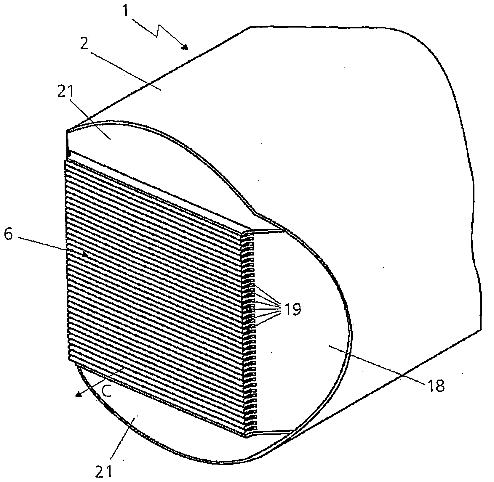
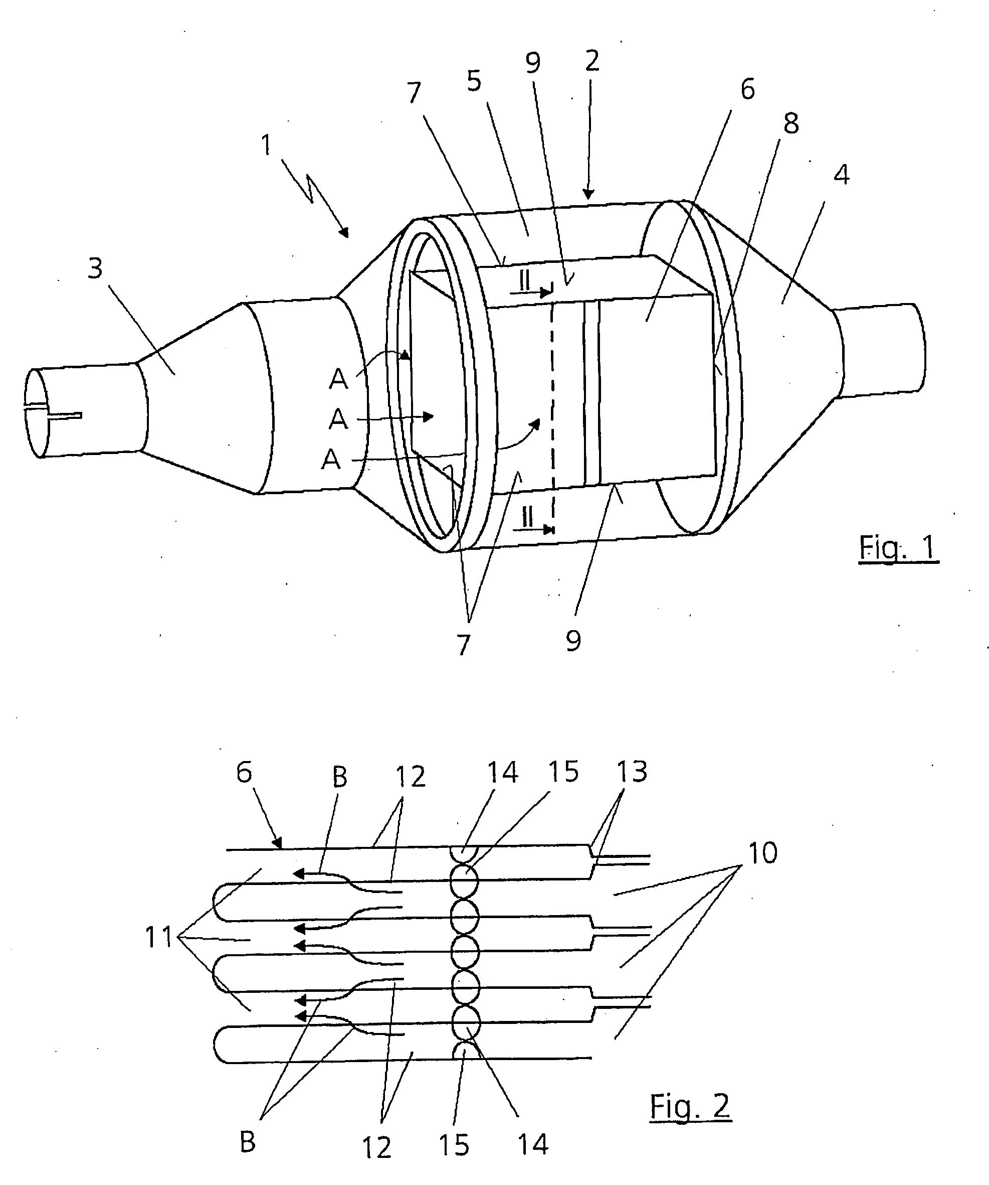
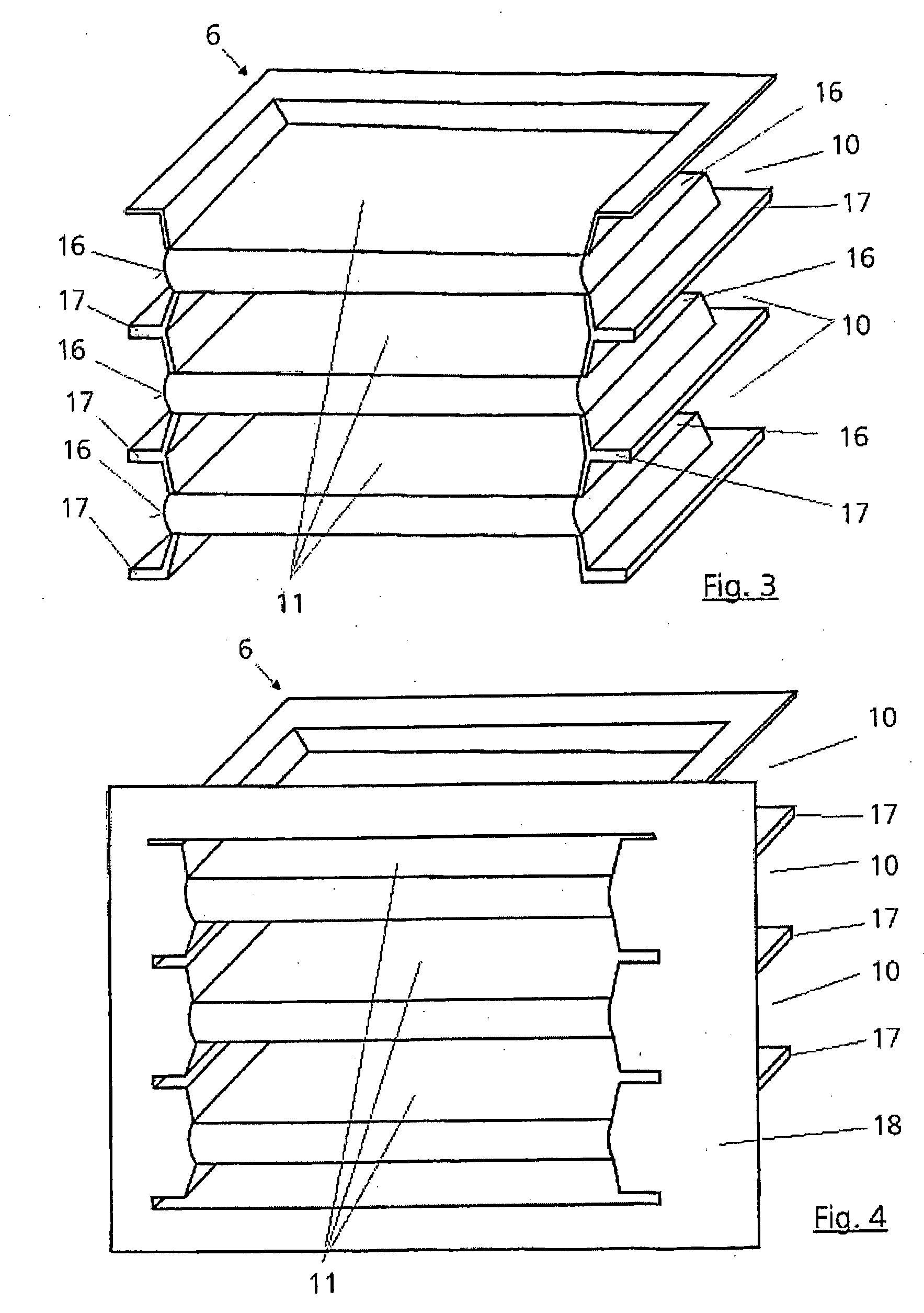
[0033]FIG. 1 shows a particulate filter 1 for separating particulates out of an exhaust gas flow of an internal combustion engine (not illustrated), which particulate filter 1 has a housing 2. In the illustrated embodiment, the housing 2 is circular in cross section over its entire length and has an inflow pipe 3 and an outflow pipe 4 which can be integrated into an exhaust line (not illustrated) of the internal combustion engine. A filter body 6 is arranged in a central section 5, situated between the inflow pipe 3 and the outflow pipe 4, of the housing 2, which filter body 6 has an inflow region 7 and an outflow region 8. The filter body 6 is of substantially quadrangular design and has respective closure plates 9 at its upper side and its lower side. The outflow region 8 is situated at that side of the filter body 6 which faces toward the outflow pipe 4, while the three remaining sides of the filter body 6 form the inflow region 7. As is illustrated by the arrows denoted by “A”, ...


PUM

PropertyMeasurementUnit
angleaaaaaaaaaa
shapeaaaaaaaaaa
pressuresaaaaaaaaaa

Abstract

A particulate filter for separating particulates out of an exhaust gas flow of an internal combustion engine has a filter body with an inflow region and an outflow region. The filter body is formed by alternately arranged inflow ducts that are open toward the inflow region and are closed toward the outflow region, and outflow ducts that are open toward the outflow region and closed toward the inflow region. The filter body has a plurality of substantially planar filter plates arranged parallel to one another. Each of the inflow ducts and the outflow ducts is formed by adjacent filter plates, and is arranged in a housing. The inflow ducts are open at at least one of their lateral regions in such a way that the inflow region extends over at least two sides of the filter body. At least one sealing element is provided for sealing off the filter body in the outflow region relative to the housing.

Description

BACKGROUND AND SUMMARY OF THE INVENTION[0001]This invention relates to a particulate filter for separating particulates out of an exhaust gas flow of an internal combustion engine.[0002]A filter for separating impurities out of exhaust gases is known from German document DE 42 34 930 A1. This filter has a filter body with a plurality of filter plates which are composed of sintered metal powder and are arranged so as to form a plurality of adjacent flow ducts. The individual filter plates are of corrugated shape and are traversed by flow in the longitudinal direction or axial direction. The corrugated shape of the filter plates results, however, in the formation of longitudinal ducts which are delimited from one another and become very quickly clogged with ash, and can therefore adversely affect the performance of the filter. A further problem of this particulate filter is the complex axial sealing arrangement via lateral clamping of the individual filter pockets, and the fact that t...

Claims


Application Information

Patent Timeline
Patent Type & Authority Applications(United States)
IPC IPC(8): B01D46/12
CPCB01D46/2418B01D2279/30B01D2271/027
Inventor FELDER, HUBERTHUETHWOHL, GEORGSCHUMACHER, UWE
Owner DAIMLER AG
Why Eureka
Try Eureka