A flow regulating valve

A technology of flow regulating valve and regulating plate, which is applied in the direction of fluid distribution valve, valve details, valve device, etc., can solve the problems such as the inability to adjust the air flow, increase the ventilation resistance, and improve the intake fan, so as to reduce adverse effects and maintain indoor air quality. The environment in the space and the effect of good energy saving effect

Active Publication Date: 2018-04-17
江苏盟杰新能源科技有限公司
View PDF7 Cites 0 Cited by
  • Summary
  • Abstract
  • Description
  • Claims
  • Application Information

AI Technical Summary

Problems solved by technology

The existing flow regulating valve has a complex structure and increases the ventilation resistance, thereby increasing the power input of the inlet fan and the outlet fan accordingly, and cannot realize the function of adjusting the air flow

Method used


Image

  • A flow regulating valve
  • A flow regulating valve
  • A flow regulating valve

Examples


Embodiment Construction

[0026] The present invention will be further described in detail below in conjunction with the accompanying drawings and examples. The following examples are explanations of the present invention and the present invention is not limited to the following examples.

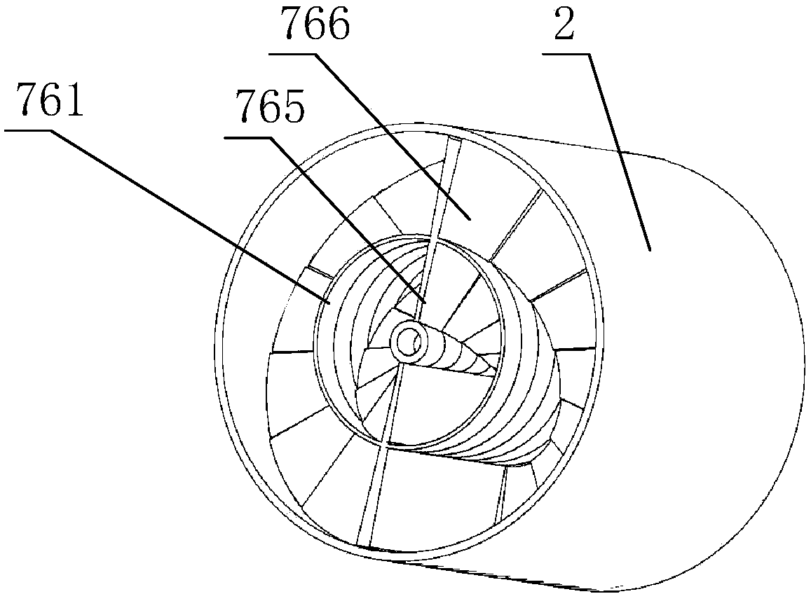
[0027] see Figure 1-Figure 12 , the flow regulating valve of this embodiment includes a coarse air intake pipe 1, a fine air intake pipe 2, a suction fan 3, a coarse exhaust pipe 4, a fine exhaust pipe 5 and an exhaust fan 6, the coarse air intake pipe 1 is connected to the suction fan 3, and the coarse air intake pipe 1 is connected to the suction fan 3. The air intake pipe 1 is connected with several fine air intake pipes 2, thereby sending the external air into several positions of the indoor space, the coarse exhaust pipe 4 is connected with the exhaust fan 6, and the coarse exhaust pipe 4 is connected with several thin exhaust pipes 5, thereby The air in several positions of the indoor space is exhausted to th...


PUM


Abstract

The invention discloses a flow control valve. The flow control valve comprises a valve shaft, a left torque motor, a valve bearing, valve toothed sleeves, double-tooth engagement sleeve parts and valve barrels, wherein the valve barrels are sequentially arranged from the left to the right so as to form a spiral channel in a rotary process of a plurality of inner regulating sheets; the size of the channel and the size of a channel opening regularly change, so that size of air flow capacity of fine air outlet tubes can be regulated; in a similar way, the size of air flow capacity of fine air inlet tubes can be regulated; and in the rotary process of the plurality of the inner regulating sheets, contact area between the air in the channel and the inner regulating sheets is continuously increased, so that the heat exchange between the fine air outlet tubes and the fine air inlet tubes can be realized by virtue of the inner regulating sheets and outer regulating sheets, thereby reducing temperature difference between the fine air inlet tube and air in the fine air inlet tube.

Description

technical field [0001] The invention relates to a flow regulating valve. Background technique [0002] Control valve, also known as control valve, in the field of industrial automation process control, is the final control element that changes the process parameters such as medium flow, pressure, temperature, liquid level, etc. by means of power operation by receiving the control signal output by the adjustment control unit. It is generally composed of actuators and valves. According to the stroke characteristics, the control valve can be divided into straight stroke and angular stroke; according to the power used by the actuator it is equipped with, it can be divided into three types according to its function and characteristics: linear characteristic, equal percentage characteristic and parabolic characteristic. The control valve is suitable for air, water, steam, various corrosive media, mud, oil and other media. English name: controlvalve, bit number usually starts wit...

Claims


Application Information

Patent Timeline
Patent Type & Authority Patents(China)
IPC IPC(8): F16K21/00F16K31/53
CPCF16K21/00F16K31/535
Inventor 石磊
Owner 江苏盟杰新能源科技有限公司
Why Eureka
Try Eureka