Thin type fan

A thin fan and fan wheel technology, used in non-variable-capacity pumps, pump devices, machines/engines, etc., can solve problems such as reducing axial thickness, reduce axial thickness, increase starting balance and rotational stability , The effect of preventing axial detachment

Active Publication Date: 2008-10-22
SUNONWEALTH ELECTRIC MACHINE IND
View PDF7 Cites 0 Cited by
  • Summary
  • Abstract
  • Description
  • Claims
  • Application Information

AI Technical Summary

Problems solved by technology

[0003] Generally speaking, the above-mentioned conventional small fans have the following disadvantages: the rotor shell and fan blades of the fan wheel are usually made by injection molding. volume, it is difficult to further reduce the axial thickness
As a result, the total axial thickness of the rotor part of the conventional small fan is usually greater than 5 mm, which relatively limits the feasibility of further designing to be lighter, thinner and shorter

Method used


Image

  • Thin type fan
  • Thin type fan
  • Thin type fan

Examples


Embodiment Construction

[0017] In order to make the above-mentioned purpose, technical features and advantages of the present invention more obvious and understandable, the preferred embodiments of the present invention are specifically cited below, and detailed descriptions are as follows in conjunction with the accompanying drawings:

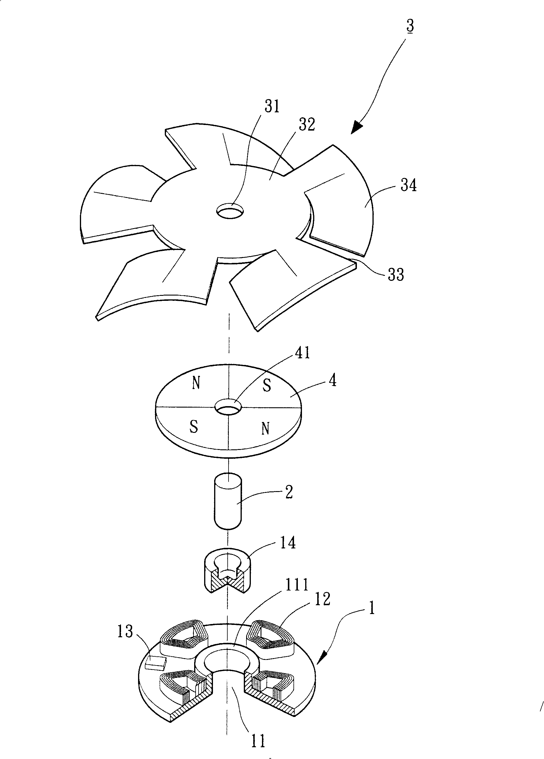
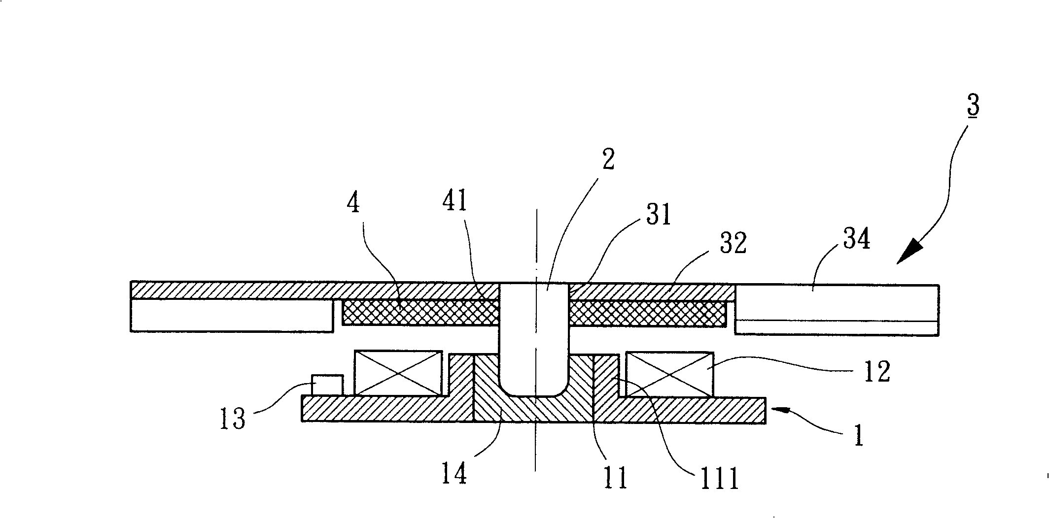
[0018] Please refer to figure 1 , 2 As shown, in the first embodiment of the present invention, a thin fan mainly includes: a base 1 , a shaft 2 , a fan wheel 3 and a sheet magnet 4 . The base 1 can be regarded as a stator component, and the shaft 2, fan wheel 3 and sheet magnet 4 can be regarded as a rotor component, and according to product requirements, the total axial thickness of the rotor component can even be reduced to less than 3 mm.

[0019] Please refer to figure 1 , 2 As shown, the base 1 is preferably made of magnetically permeable material, such as iron or iron alloy. The base 1 is provided with a shaft hole 11 , at least one coil 12 , a driving ele...


PUM


Abstract

A thin fan is composed of a base with an axle hole and at least one coil, a blade wheel consisting of an annular plate and multiple curved blades, a magnet sheet with at least one pair of N and S poles on its surface, and an axle.

Description

technical field [0001] The invention relates to a fan, in particular to a fan wheel directly composed of a ring plate and a plurality of bent fan blades, which can omit the existing rotor shell, further reduce the overall axial thickness, make the assembly simple and reliable, and increase the starting balance of the fan wheel and a thin fan with stable rotation. Background technique [0002] Conventional fans, such as the invention patent of US Pat. No. 5,2 17,351 "Small Fan", include a housing and a fan wheel. There is a base inside the casing, and a shaft tube and two coils are arranged on the base, a bearing is arranged inside the shaft tube, and the two coils are flat. The fan wheel has a rotor shell, a plurality of fan blades, a shaft and a ring magnet. The rotor shell is in the shape of an inverted bowl, and the fan blades are arranged radially at equal distances on its outer peripheral surface. One end of the shaft rod is fixed in the center of the rotor shell, an...

Claims


Application Information

Patent Timeline
Patent Type & Authority Patents(China)
IPC IPC(8): F04D25/08
Inventor 洪银树尹佐国
Owner SUNONWEALTH ELECTRIC MACHINE IND
Why Eureka
Try Eureka