Display device

A technology for display devices and grayscale reference voltages, applied to static indicators, instruments, televisions, etc., can solve the problems of source driver 150 output voltage reduction, and achieve the effect of preventing circuit scale from becoming larger and suppressing potential reduction

Inactive Publication Date: 2019-05-03
SHARP KK
View PDF6 Cites 0 Cited by
  • Summary
  • Abstract
  • Description
  • Claims
  • Application Information

AI Technical Summary

Problems solved by technology

As a result, the output voltage of the source driver 150 is lowered by limiting the current required to output the gradation voltage, and a voltage lower than the original voltage value is applied to the source line.

Method used


Image

  • Display device
  • Display device
  • Display device

Examples


Embodiment Construction

[0049]

[0050]

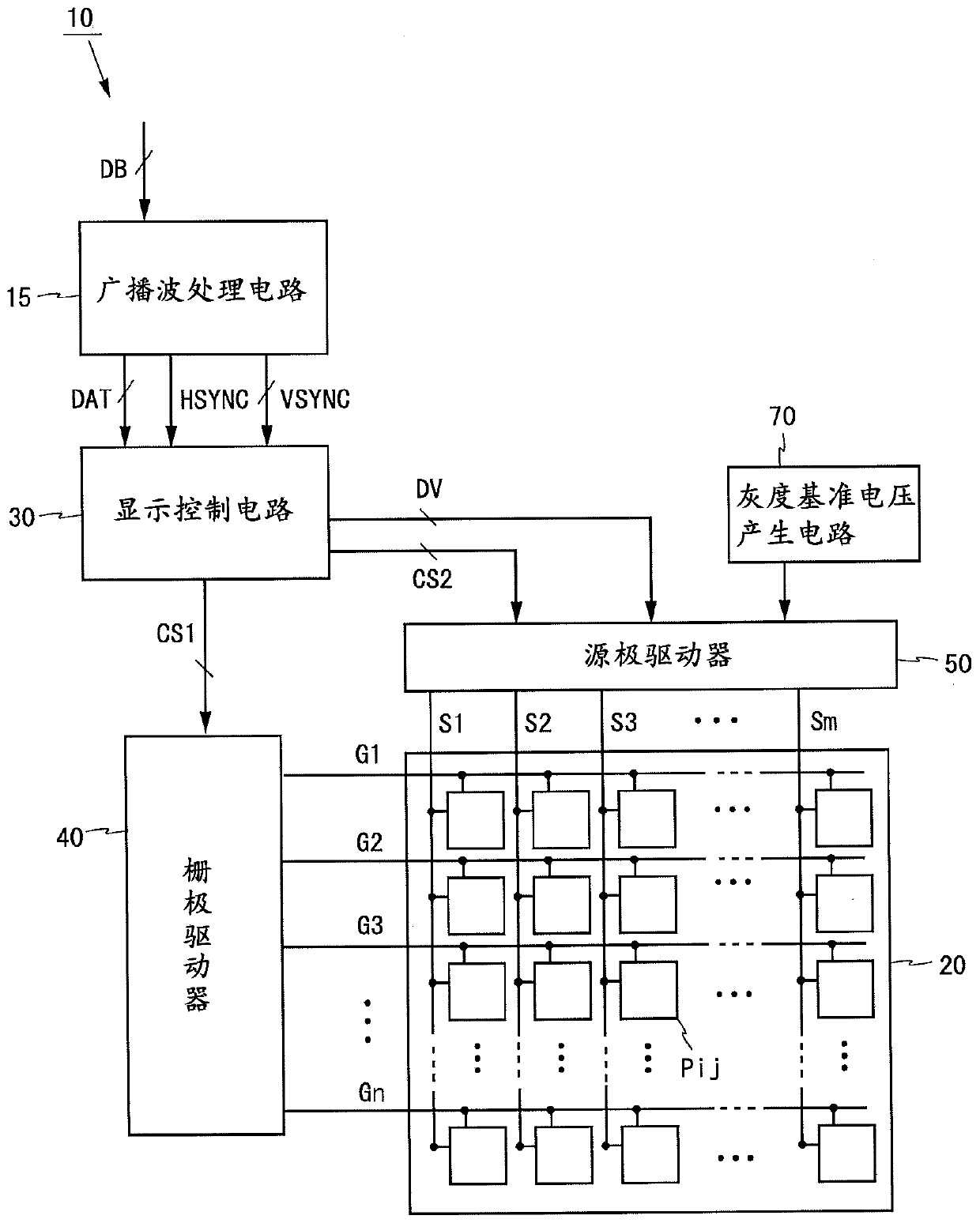
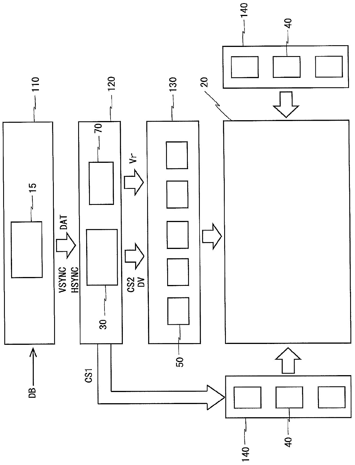
[0051] figure 1 It is a block diagram showing the configuration of the liquid crystal display device 10 according to the embodiment of the present invention. Such as figure 1 As shown, the liquid crystal display device 10 includes a broadcast wave processing circuit 15, a liquid crystal panel 20, a display control circuit 30, a gate driver 40 (also called "scanning signal line driver circuit"), a source driver 50 (also called "image signal line drive circuit"), and a gray scale reference voltage generation circuit 70.

[0052] The liquid crystal panel 20 includes n gate lines G1˜Gn (also referred to as “scanning signal lines”), m source lines S1˜Sm (also referred to as “image signal lines”), and (m×n) pixels Pij (m and n: integers of 2 or more, i: integers of 1 or more and n or less, j: integers of 1 or more and m or less). The gate lines G1 to Gn are arranged in parallel to each other, and the source lines S1 to Sm are arranged in parallel to each o...


PUM

PropertyMeasurementUnit
capacitanceaaaaaaaaaa

Abstract

Provided is a video signal line driving circuit that enables an image of high display quality to be displayed even when identical gradation voltages are simultaneously selected as analog image signals. A voltage ladder (87) in a source driver (50) has formed therein a gradation voltage compensation line (91) that extends to the outside of the source driver (50) from an output terminal for outputting a generated gradation voltage. This gradation voltage compensation line (91) is grounded outside the source driver (50) via a voltage compensation capacitor (90). By this configuration, even when identical gradation voltages are simultaneously selected as analog image signals, the necessary current is complemented from the voltage compensation capacitor (90) to the voltage ladder (87), therebyinhibiting a drop in potential at the output terminal for outputting the gradation voltage.

Description

technical field [0001] The present invention relates to a display device, in particular to an active matrix type display device for gray scale display. Background technique [0002] A display device such as a liquid crystal display device includes a video signal line driver circuit (also referred to as a "source driver") that generates gray-scale voltages based on a gray-scale reference voltage, and selects a gray-scale voltage corresponding to the video signal from the generated gray-scale voltages. voltage, which is applied to image signal lines (also referred to as "source lines") as analog image signals; and a scanning signal line driving circuit (also referred to as "Gate lines") are sequentially activated to write the analog image signals applied to the source lines into the pixels, and the high-level scan signals are sequentially applied to the gate lines. [0003] In such a display device, in order to generate an analog video signal corresponding to a digital video ...

Claims


Application Information

Patent Timeline
Patent Type & Authority Applications(China)
IPC IPC(8): G09G3/36G02F1/133G09G3/20H04N5/66
CPCG09G3/3688G09G3/3696G09G2320/0223G09G2300/0876G09G3/3674G09G3/36G09G3/20
Inventor 长坂幸二佐佐木崇中本达哉
Owner SHARP KK
Why Eureka
Try Eureka