Legged traveling in a bipedal upright form is disadvantageous in that the robot is unstable and difficult in posture control and walking control when compared with traveling of the crawler type or four- or six-legged traveling.
Stumbling of the
machine body signifies interruption of a work being performed, and considerable labor and time are required until the robot stands up uprightly from the stumbling state and resumes the work.
Further, there is the possibility that the stumbling may critically damage the robot body and also damage a substance with which the stumbling robot collides.
An ordinary upright posture as a basic posture of a robot which performs upright walking is unstable in the first place.
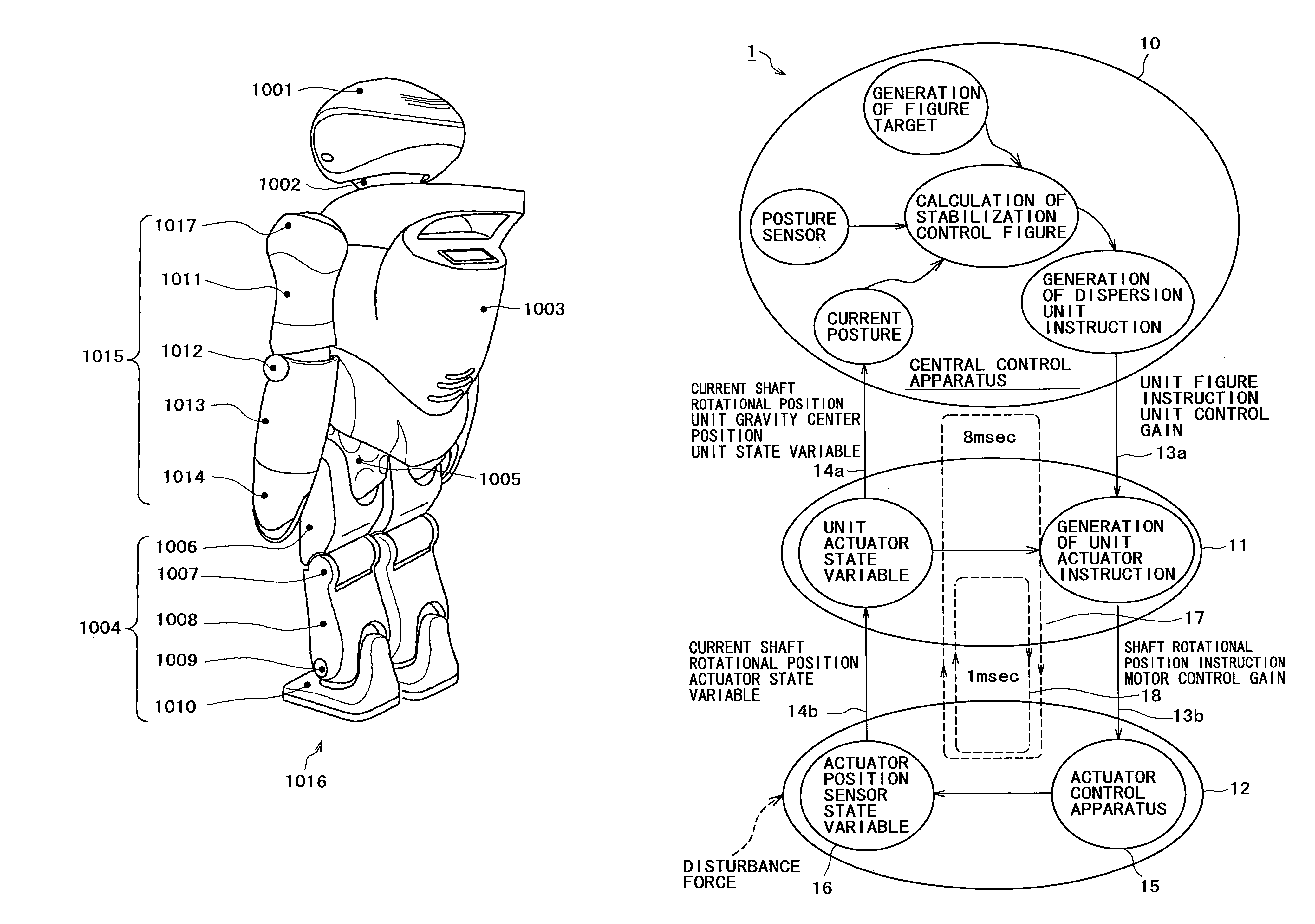
However, where the central control apparatus calculates all control instructions regarding a motion of the robot, a
heavy load is imposed on the central control apparatus.
Particularly while it is demanded to form a integrated control section from a miniaturized
processing circuit, it is difficult to increase the number of parameters to be used for a calculation process to calculate control instructions at a high speed in response to various state variations of the joint parts.
Further, if it is presumed to use the
control flow illustrated in FIG. 33 to control a motion of a robot which has the structure shown in FIG. 31, then it is difficult to lay
signal transmission cables for transmitting control instructions to the actuators for driving the joint parts from the central control apparatus serving as a integrated control section.
Further, it is difficult to use only the central
processing apparatus to rapidly calculate control instructions for attenuating inadvertent external force such as an
impact and transmit the newly calculated control instructions at a high speed to the actuators.
In short, it is difficult to reduce the time required for communication of various kinds of information between the central control apparatus and the driving sections.
Further, it is difficult to drive, after external force is applied, the joint parts to operate rapidly in an
interlocking relationship with each other to moderate the external force to secure the stability in posture control of the robot and prevent otherwise possible damage to the robot by the external force.
Therefore, where the robot apparatus is a multi-axis robot apparatus having a high degree of freedom, a calculation imposes a heavy burden on the central control apparatus.
Therefore, it is difficult for the central control apparatus to respond on the real time basis, and the central control apparatus cannot cope with a sudden variation, for example, by a collision.
Since the conventional robot apparatus has a single hierarchy control structure, the
processing is concentrated on the central control apparatus, and therefore, where multi-axis control is intended, there is a limitation to a high speed real
time response.
(1) Since the central control apparatus executes control of all shafts on the real time basis, high speed communication and high speed calculation processing are required, and therefore, a large circuit scale is required for the central control apparatus.
(2) Since both of reflex
movement control of a terminal end and
movement control of the entire robot apparatus are processed in an equal control cycle, the performance is poor.
Further, the conventional robot apparatus has no degree of freedom at the soles thereof, and each sole has a rubber member adhered to a flat face thereof to cope with an uneven
road surface and secure friction to eliminate an otherwise possible slip.
Further, although a structure that a degree of freedom of a
toe is provided for the sole is available, the sole cannot move in response to an uneven configuration of the ground surface.
Therefore, the robot apparatus has a problem that it is unstable particularly on a convex ground surface and cannot maintain its posture but may stumble.
In other words, the robot apparatus has a limitation to a response thereof to a collision which occurs when the sole is brought into contact with a rough
road surface upon walking, and cannot make a reflex movement of a terminal end thereof.
However, most of such attempts are directed to examination only of the
algorithm but not to the
signal processing or the configuration of a
control system.

