Method for minimizing the error of a measurable quantity

A technique of minimizing the measured variable, applied to measuring devices, instruments, special recording/indicating devices, etc., to achieve the effect of providing stability and avoiding feedback

Inactive Publication Date: 2008-10-22
CS CLEAN SYST AG
View PDF2 Cites 0 Cited by
  • Summary
  • Abstract
  • Description
  • Claims
  • Application Information

AI Technical Summary

Problems solved by technology

In this case, the result is only optimal for signals in the particular range

Method used


Image

  • Method for minimizing the error of a measurable quantity
  • Method for minimizing the error of a measurable quantity
  • Method for minimizing the error of a measurable quantity

Examples


Embodiment Construction

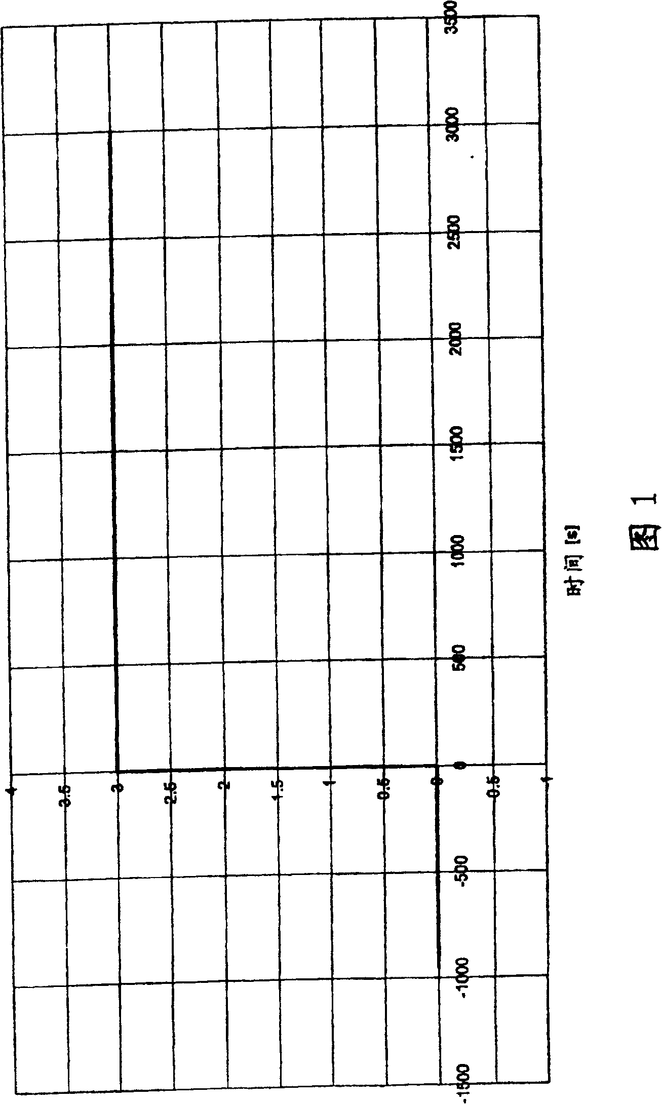
[0026] Figure 1 shows the ideal situation for a noise-free signal. At t=0 the signal performs a jump from 0 to 3 MHz and then remains constant.

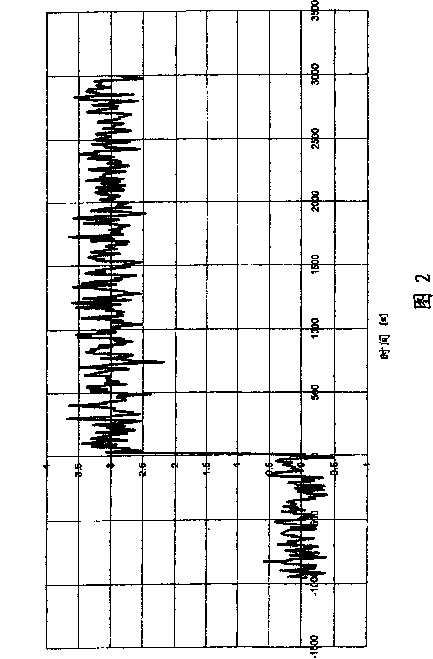
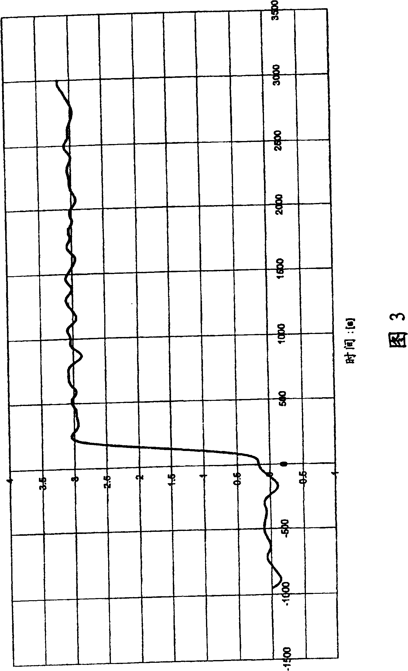
[0027] Figures 2, 3, and 4 provide realistic illustrations. In this case, the signal shown in Fig. 1 is shown as a signal with noise of different bandwidth and is passed through low-pass filters of different bandwidth for this purpose. The bandwidth in Fig. 1 is 25MHz [sic; 2], the bandwidth in Fig. 3 is 3MHz, and the bandwidth in Fig. 4 is 0.4MHz. As can be deduced from Figures 2, 3, and 4, the higher the bandwidth of the signal, the higher the noise amplitude; however, the higher the bandwidth frequency, the faster the jump at t=0.

[0028] Figure 5 shows the error signal with 3MHz bandwidth. The error signal is the difference between the information component shown in Figure 1 and the measured signal after passing through a low-pass filter (shown in Figure 3, which has a bandwidth of 3MHz). The error corresponds to the full he...


PUM


Abstract

In the framework of the method for minimizing the error of a measured variable, particularly a signal to be measured using filtering at variable bandwidth, the bandwidth is regulated on the basis of a physical criterion inherent to the method in such a ways that signal changes not caused by noise are recognized as early as possible.

Description

technical field [0001] The invention relates to a method for minimizing the error of a measured variable. Background technique [0002] Usually, the measured signal has noise components in addition to information components. The noise amplitude and / or noise content in the signal under test is generally reduced at the expense of response time by means of a low-pass filter. [0003] Therefore, when evaluating the signal under test, it is often necessary to find a compromise between lower noise amplitude and shorter response time. [0004] According to the prior art, a filter with a fixed high bandwidth is often used, which has a short response time; however, such filters have a high noise amplitude. However, the noise amplitude can be reduced by using a filter with a fixed low bandwidth, but it has been found that this procedure will result in a longer response time. [0005] Therefore, if a low noise amplitude is required in addition to a short response time, a filter with...

Claims


Application Information

Patent Timeline
Patent Type & Authority Patents(China)
IPC IPC(8): G01D3/032
CPCG01D3/032
Inventor 琼璩·威雀尔
Owner CS CLEAN SYST AG
Why Eureka
Try Eureka