Ride control constant contact side bearing arrangement

A long-stroke, basic-body technology, applied in the direction of the device that moves laterally between the chassis and the bogie, to reduce weight, improve inspection capabilities, and reduce the need for

Active Publication Date: 2008-11-12
AMSTED RAIL CO INC
View PDF7 Cites 2 Cited by
  • Summary
  • Abstract
  • Description
  • Claims
  • Application Information

AI Technical Summary

Problems solved by technology

Previous standards such as M-948-77

Method used


Image

  • Ride control constant contact side bearing arrangement
  • Ride control constant contact side bearing arrangement
  • Ride control constant contact side bearing arrangement

Examples


Embodiment Construction

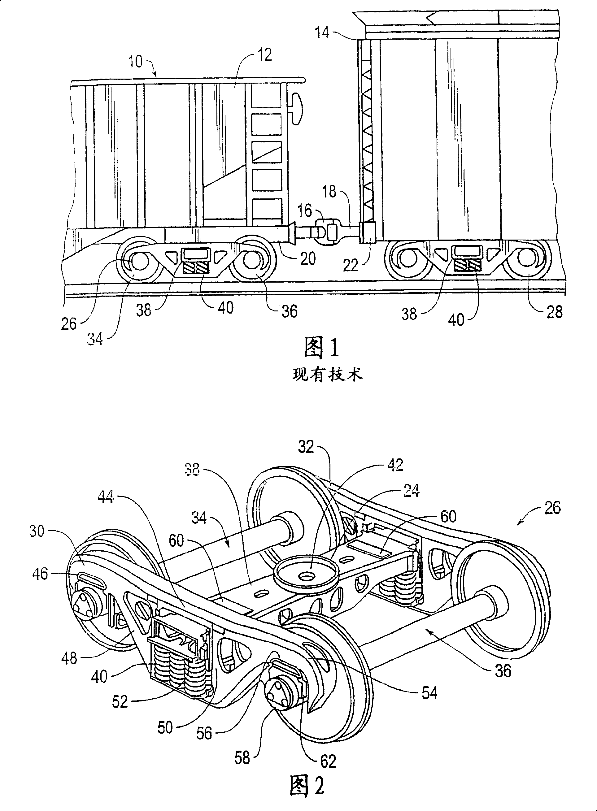
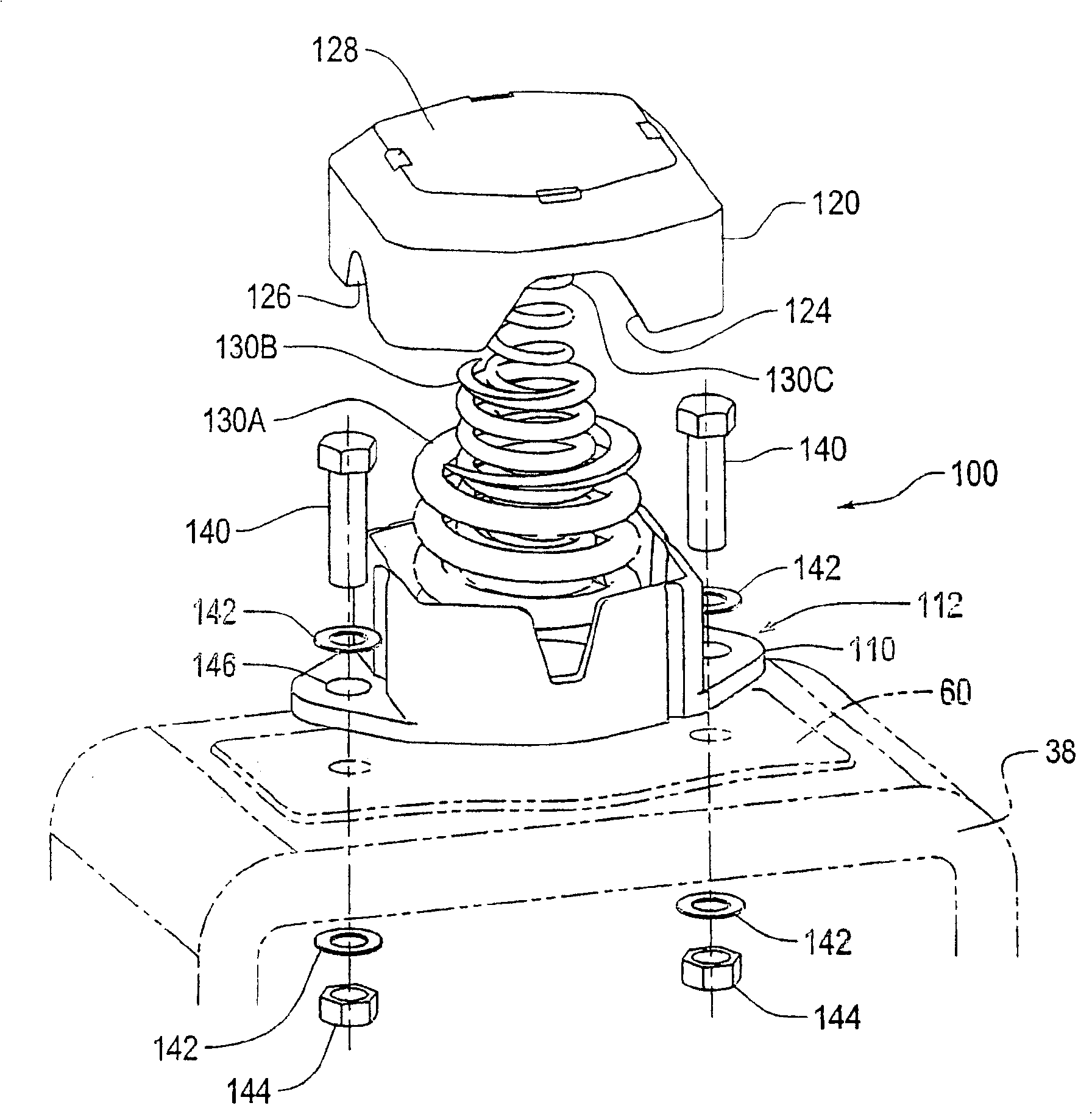
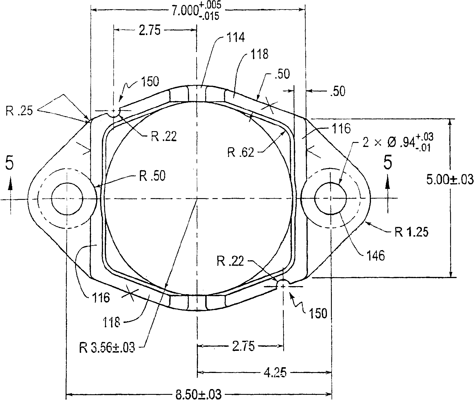
[0056] Refer to attached image 3 -8, The first embodiment according to the present invention will be described. Side bearing member 100 has a longitudinal major axis coincident with the longitudinal axis of the railroad car. That is, when the side bearing is mounted to the railcar truck backing plate 38 ( Figure 4 Only a portion is shown), the side bearing main shaft is perpendicular to the backing plate longitudinal axis. The main components of the side bearing component 100 include a base body 110, a cap 120, and one or more elastic actuating components 130, such as a spring or an elastomer element. In the exemplary embodiment, three springs are provided here as the actuating elements, an outer spring 130A, a middle spring 130B and an inner spring 130C, each having a different spring constant to provide an overall combined load rate.

[0057] The base body 110 is secured to the backing plate 38 by suitable means. As shown, the base 110 is bolted to the backing plate 38 ...


PUM

PropertyMeasurementUnit
Load rateaaaaaaaaaa

Abstract

A long travel constant contact side bearing for railway cars provides better handling characteristics, achieving improved tracking and curving through use of various combinations of features. Such a long travel side bearing is able to meet recent stringent American Association of Railroads standards, such as M-976. Lowered spring rates, preferably less than 6,000 lb/in., help with stability and reduce set-up sensitivity. Reduced cap and base dimensions and spring design help achieve travel of at least 5/8'. A visual inspection windows allows ready inspection. Increased service life and wear characteristics are obtained by addition of hardened wear surfaces, improved tolerances, changes to Grade E steel, increase of top contact surface flatness and coped top surface peripheral edges. Standardized sets of spring components can be mixed and matched, requiring fewer specialty parts. Interchangeability of improper components can be prevented by a combination of keying features and/or spring lockout features.

Description

technical field [0001] The present invention relates to an improvement in the design of side bearings for mounting on railway vehicle truck bolsters which allow long travel, reduced physical weight, improved hunting and bending characteristics, and various safety features. Background technique [0002] In a conventional railroad freight car, as shown in Figure 1, railcars 12, 14 are connected at their ends by couplers 16, 18, each coupler 16, 18 along hydraulic shock absorbers or other shock absorbing components (not shown in the drawings). ) are matched with draw beam 20,22 respectively. The drawbeams 20 , 22 are disposed at the ends of the railcar center beams and include center plates retained on the bowl-shaped center plates of the railroad car trucks 26 , 28 . [0003] As best illustrated in FIG. 2 , each conventional vehicle truck 26 includes a pair of sideframes 30 , 32 supported on wheelsets 34 , 36 . A hollow backing plate 38 extends between the side frames and is...

Claims


Application Information

Patent Timeline
IPC IPC(8): B61F5/14
CPCB61F5/14
Inventor 拉尔夫·H·肖尔丹·施尼尔斯
Owner AMSTED RAIL CO INC
Why Eureka
Try Eureka