Method and circuit for power factor correction(PFC)
A power factor correction and circuit technology, which is applied in the direction of output power conversion device, irreversible AC power input to DC power output, electrical components, etc., can solve the problem of current deviation from the sine envelope, etc., to prevent overcurrent Effect
- Summary
- Abstract
- Description
- Claims
- Application Information
AI Technical Summary
Problems solved by technology
Method used
Image
Examples
Embodiment Construction
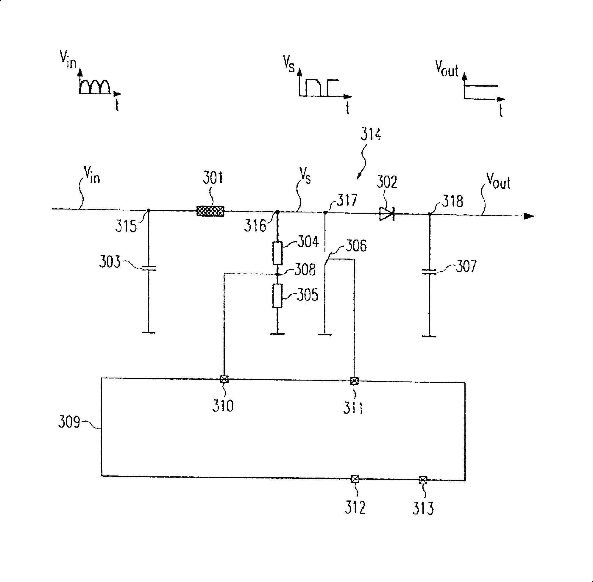
[0031] image 3 In , the structure of the power factor correction circuit 314 according to the present invention is shown.
[0032] Input AC voltage V in Filtered by the filter capacitor 303 and fed to the inductor 301, ie the coil. An inductor 301 is connected in series before a diode 302 between an input 315 and an output 318 . The input AC voltage V is provided at the input terminal 315 in , while the output DC voltage V can be obtained at the output terminal 318 out . The output DC voltage capacitor 307 is connected between the output terminal 318 and ground. A controllable switch 306 is connected at a connection 317 between the inductor 301 and the diode 302 .
[0033] When switch 306 is closed, inductor 301 is shorted to ground and diode 302 is off. The inductor 301 is then charged so that energy is stored in the inductor 301 .
[0034] On the other hand, when switch 306 is off, diode 302 is on. Then, the inductor 301 is discharged into the output DC voltage cap...
PUM
 Abstract
Description
Claims
Application Information
 - R&D
- Intellectual Property
- Life Sciences
- Materials
- Tech Scout
- Unparalleled Data Quality
- Higher Quality Content
- 60% Fewer Hallucinations
Browse by: Latest US Patents, China's latest patents, Technical Efficacy Thesaurus, Application Domain, Technology Topic, Popular Technical Reports.
© 2025 PatSnap. All rights reserved.Legal|Privacy policy|Modern Slavery Act Transparency Statement|Sitemap|About US| Contact US: help@patsnap.com


