
Method and circuit for power factor correction(PFC)

A power factor correction and circuit technology, applied in output power conversion devices, irreversible AC power input conversion to DC power output, electrical components and other directions, can solve the problem of current deviation from the sinusoidal envelope, etc., to prevent overcurrent. Effect

Active Publication Date: 2005-11-30
TRIDONIKATKO GMBKH & KO KG
View PDF1 Cites 11 Cited by
  • Summary
  • Abstract
  • Description
  • Claims
  • Application Information

AI Technical Summary

Problems solved by technology

However, this is not always the ideal situation and the current can even deviate considerably from the sinusoidal envelope

Method used


Image

  • Method and circuit for power factor correction(PFC)
  • Method and circuit for power factor correction(PFC)
  • Method and circuit for power factor correction(PFC)

Examples


Embodiment Construction

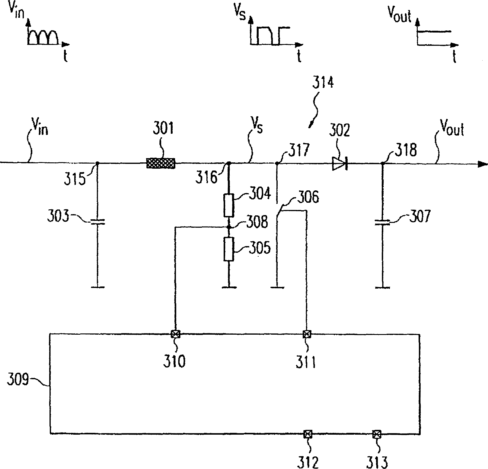
[0031] image 3 In , the structure of the power factor correction circuit 314 according to the present invention is shown.

[0032] Input AC voltage V in Filtered by the filter capacitor 303 and fed to the inductor 301, ie the coil. An inductor 301 is connected in series before a diode 302 between an input 315 and an output 318 . The input AC voltage V is provided at the input terminal 315 in , while the output DC voltage V can be obtained at the output terminal 318 out . The output DC voltage capacitor 307 is connected between the output terminal 318 and ground. A controllable switch 306 is connected at a connection 317 between the inductor 301 and the diode 302 .

[0033] When switch 306 is closed, inductor 301 is shorted to ground and diode 302 is off. The inductor 301 is then charged so that energy is stored in the inductor 301 .

[0034] On the other hand, when switch 306 is off, diode 302 is on. Then, the inductor 301 is discharged into the output DC voltage cap...


PUM


Abstract

The invention relates to a fairing input alternating voltage provided by an inductive resistor (301) in order to correct the power factor in the alternating voltage / direct voltage power converter. The inductive resistor (301) is selectively charged or discharged via a switch (306). According to the comparative result of the direct voltage and the fixed reference voltage, the closing time interval of the switch (306) and the charge time of the inductive resistor (301) are controlled. Therefore, the switch (306) is cut to ensure the inductive resistor (301) discharge till the current through the inductive resistor (301) to zero. According to the invention, during the interval of the cut time of the switch (306), the signal at the measuring point (308) is used to educe the zero crossing of the output direct voltage and the current through the inductive resistor (301).

Description

technical field [0001] The present invention relates to methods and apparatus for power factor correction (PFC). [0002] The technical field of the invention relates in particular to power factor correction for alternating current (a.c.) voltage / direct current (d.c.) voltage power converters. Background technique [0003] Power factor correction affects the way electrical equipment draws current from a power source. As is known, the mains AC voltage has a sinusoidal time form. Ideally, the current drawn from the power supply should also have a sinusoidal time form. However, this is not always the case and the current can even deviate considerably from the sinusoidal envelope. If the current drawn is not sinusoidal, harmonics will be generated in the power supply. These harmonic currents in the power supply are reduced by power factor correction circuits. [0004] In order to obtain a sinusoidal input current in phase with the mains AC voltage, the prior art proposes th...

Claims


Application Information

Patent Timeline
Patent Type & Authority Applications(China)
IPC IPC(8): H02M1/00H02M1/42
CPCY02B70/126H02M2001/0009H02M1/4225Y02B70/10H02M1/0009
Inventor 甘特尔·马兰特斯蒂芬·朱戴尔科赫
Owner TRIDONIKATKO GMBKH & KO KG
Learn More