Hand crimp connecting tool

A technology of crimping tools and crimping terminals, applied in the direction of connections, electrical components, circuits, etc.

Inactive Publication Date: 2008-11-26
TYCO ELECTRONICS JAPAN GK
View PDF7 Cites 0 Cited by
  • Summary
  • Abstract
  • Description
  • Claims
  • Application Information

AI Technical Summary

Problems solved by technology

However, the manual crimping tool disclosed in Patent Document 1 cannot support the crimping portion of the crimping terminal but the portion protruding from the crimping portion as described above, so it cannot support only the crimping portion. The problem of crimping the state of the terminal

Method used


Image

  • Hand crimp connecting tool
  • Hand crimp connecting tool
  • Hand crimp connecting tool

Examples


Embodiment Construction

[0022] Next, embodiments of the present invention will be described.

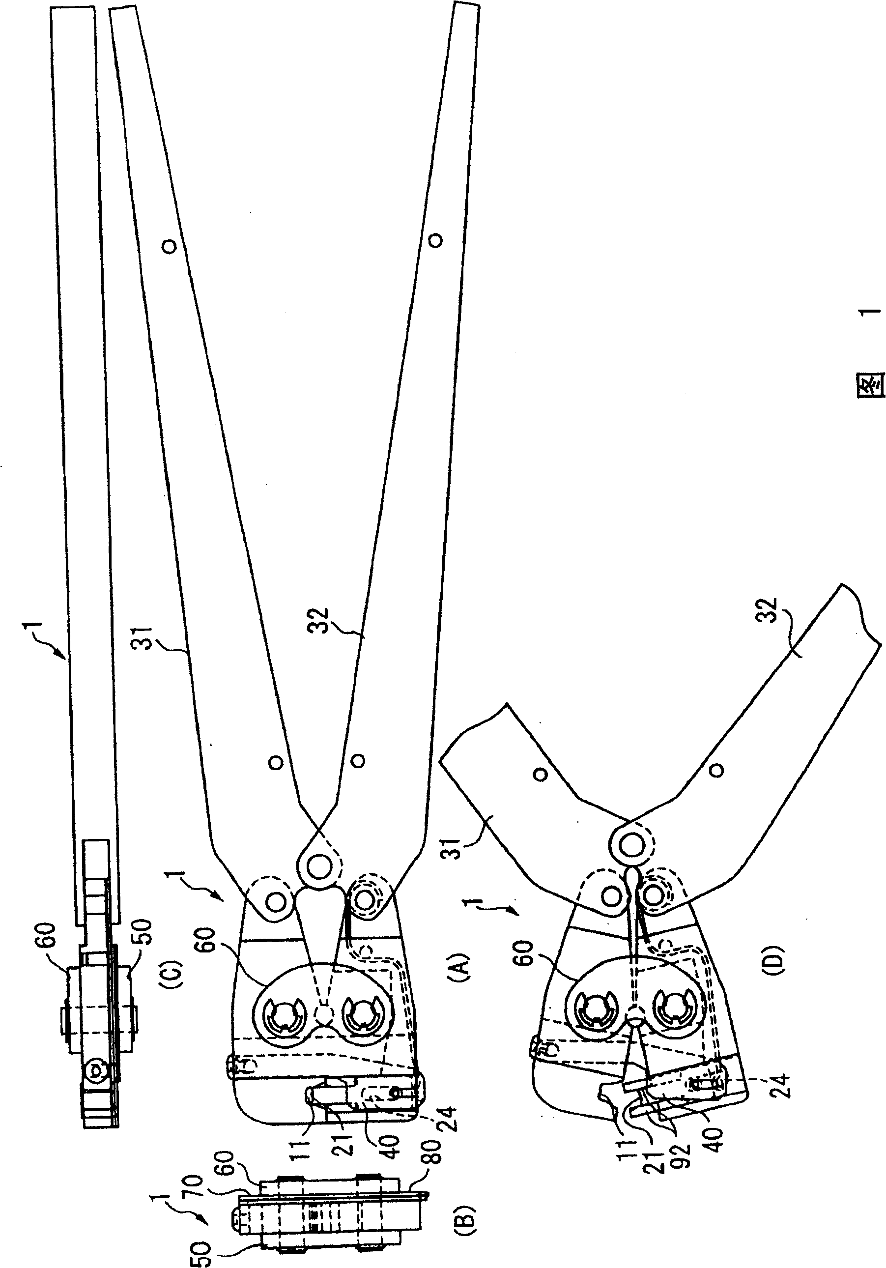
[0023] Fig. 1 is an overall structural view of the manual crimping tool of the present invention. In this FIG. 1 , FIG. 1(A) is a front view, FIG. 1(B) is a side view, and FIG. 1(C) is a top view. In addition, Fig. 1(D) is a front view showing a state in which the bead portion and the anvil are opened.

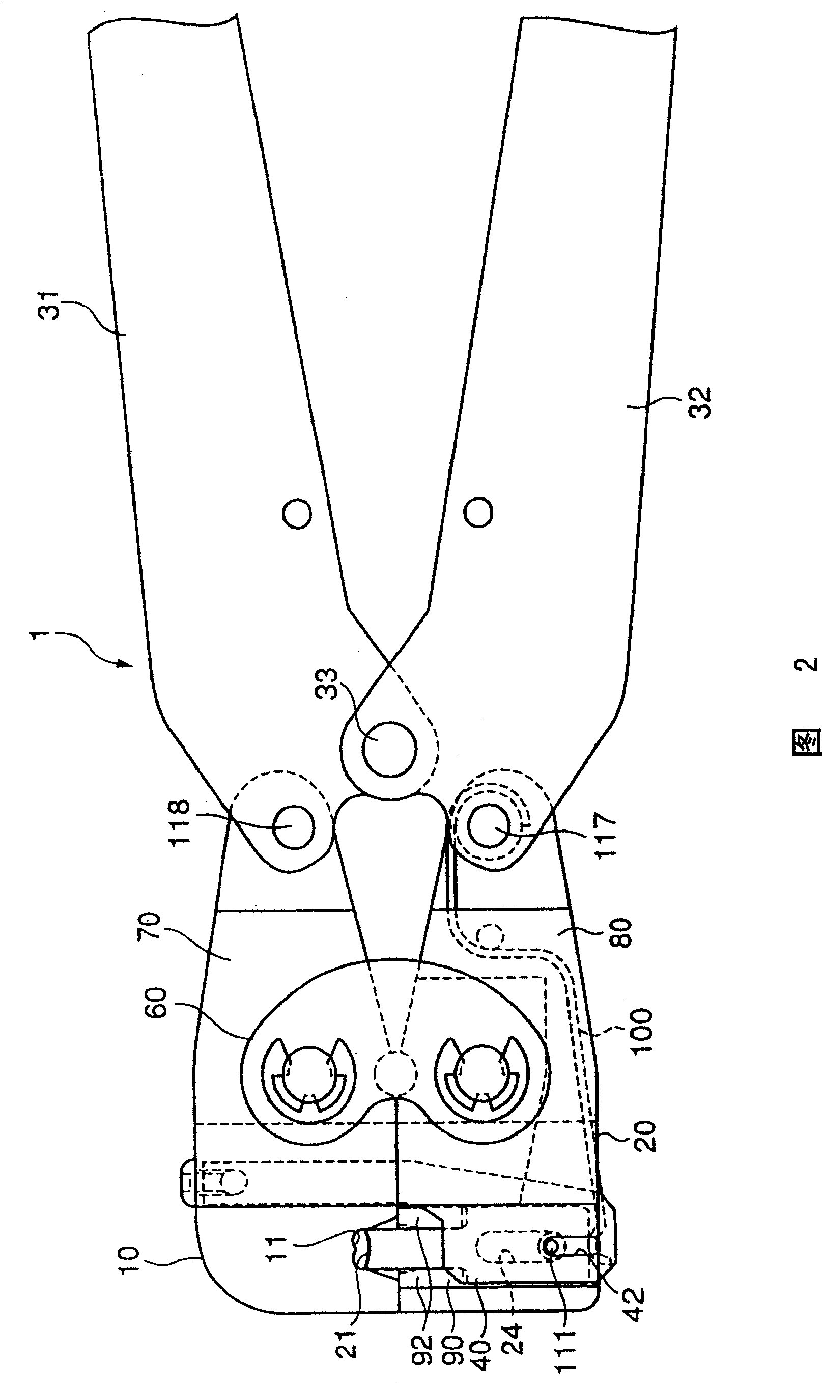
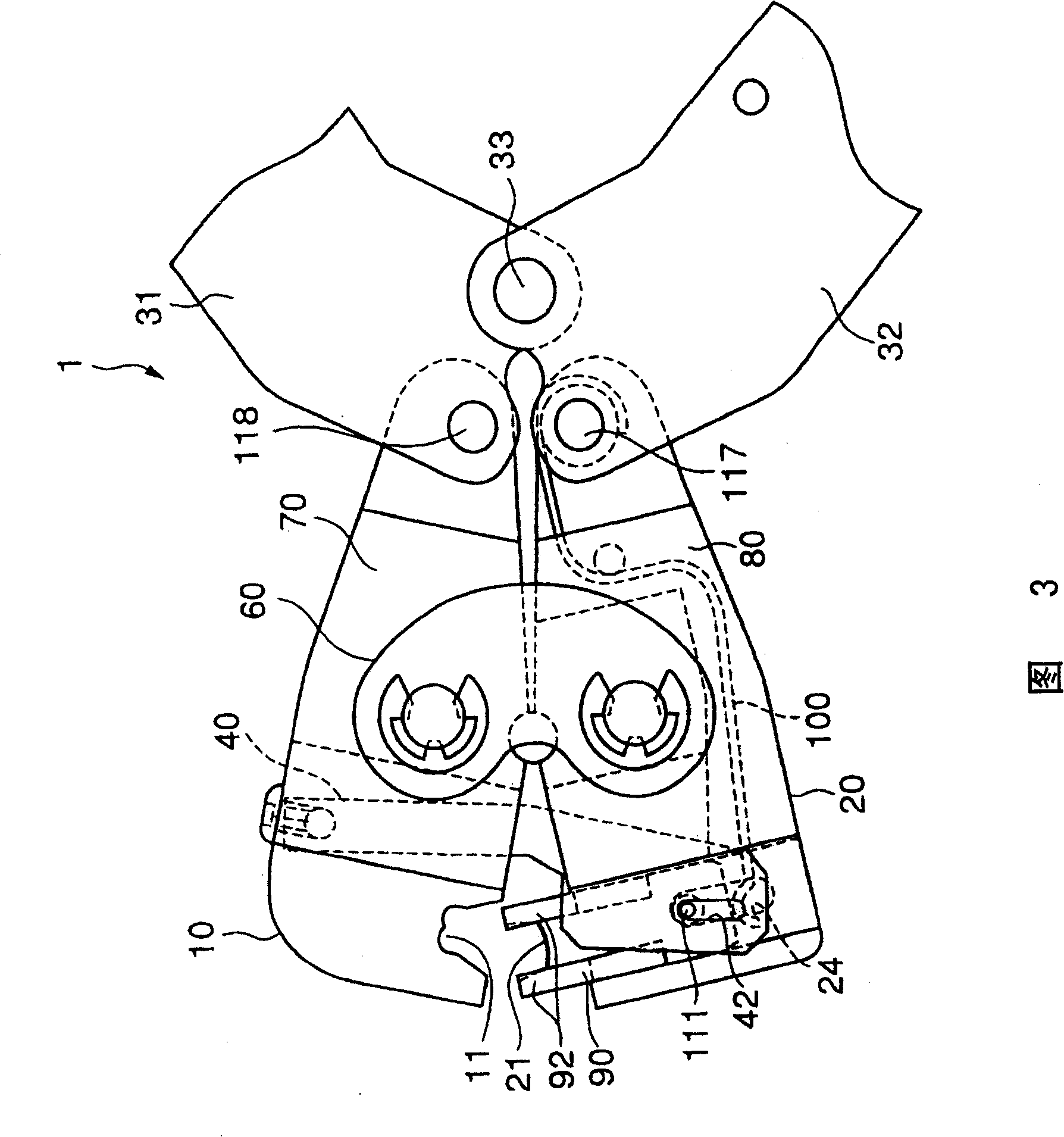
[0024] In addition, FIG. 2 is an enlarged front view of the first and second jaws in a closed state. Fig. 3 is an enlarged front view of first and second jaws in an open state.

[0025] In addition, FIG. 4 is an assembly view showing components of the manual crimping tool shown in FIGS. 1 to 3 . Figure 5 This is an enlarged view of a crimp terminal with only the crimp portion. Figure 6 It is an enlarged view of a slider used in the manual crimping tool shown in FIGS. 1 to 4 .

[0026] The manual crimping tool of this embodiment, even if Figure 5 Even the crimp terminal having the shape shown above, t...


PUM


Abstract

The invention provides a manual crimping tool which has a crimper and an anvil and crimps a crimp style terminal arranged between these crimper and anvil and which can crimp even the crimp style terminal having only crimping part by controlling the posture of the crimp style terminal until completion of crimping. The manual crimping tool is equipped with a first jaw 10 having a crimper 11 and a second jaw 20 having the anvil 21, handles 31, 32 for crimping the crimp style terminal arranged between the crimper 11 and the anvil 21, and a slider 90 fitted to the second jaw 20 capable of sliding and supporting the crimp style terminal. The slider 90 has a base part 91 which slides along the side face 20a of the second jaw 20 and a pair of terminal support members 92 which are linked integrally with the base part 91 and support the crimp style terminal by being arranged on both sides of the anvil 21, and is urged by a spring toward the first jaw 10 by a spring member 100 fixed to the second jaw 20.

Description

technical field [0001] The present invention relates to a manual crimping tool having a crimping portion and an anvil, and crimping a crimping terminal arranged between the crimping portion and the anvil. Background technique [0002] Conventionally, crimping terminals that are crimped and connected to the core wires of electric wires have been used. As devices for crimping these crimping terminals, there are automatic machines, but manual crimping tools, for example, are also used for on-site operations. . [0003] The manual crimping tool is configured such that a crimping terminal is disposed between a crimping portion and an anvil included in the manual crimping tool, and the crimping terminal is clamped between the crimping portion and the anvil by operating a handle to perform crimping. catch. [0004] Here, when using a manual crimping tool to crimp a crimp terminal, the crimp terminal once configured cannot be moved before crimping, and must maintain a correct post...

Claims


Application Information

Patent Timeline
IPC IPC(8): H01R43/042
Inventor 中茂
Owner TYCO ELECTRONICS JAPAN GK
Why Eureka
Try Eureka