
Normally-white TN-mode LCD device

A device and mode technology, applied in the direction of nonlinear optics, instrumentation, optics, etc., can solve the problems of deteriorating viewing angle characteristics of LCD devices and reducing contrast, and achieve the effects of increasing viewing angle, improving white brightness, and improving image quality

Active Publication Date: 2008-12-03
BEIHAI HKC OPTOELECTRONICS TECH CO LTD
View PDF5 Cites 0 Cited by
  • Summary
  • Abstract
  • Description
  • Claims
  • Application Information

AI Technical Summary

Problems solved by technology

[0005] In an LCD device, it is well known that the refractive index anisotropy of the LC layer reduces the contrast in oblique viewing directions so as to deteriorate the viewing angle characteristics of the LCD device.

Method used


Image

  • Normally-white TN-mode LCD device
  • Normally-white TN-mode LCD device
  • Normally-white TN-mode LCD device

Examples


Embodiment Construction

[0037] Now, the present invention will be described more specifically with reference to the accompanying drawings, wherein like constituent elements are denoted by like reference numerals throughout.

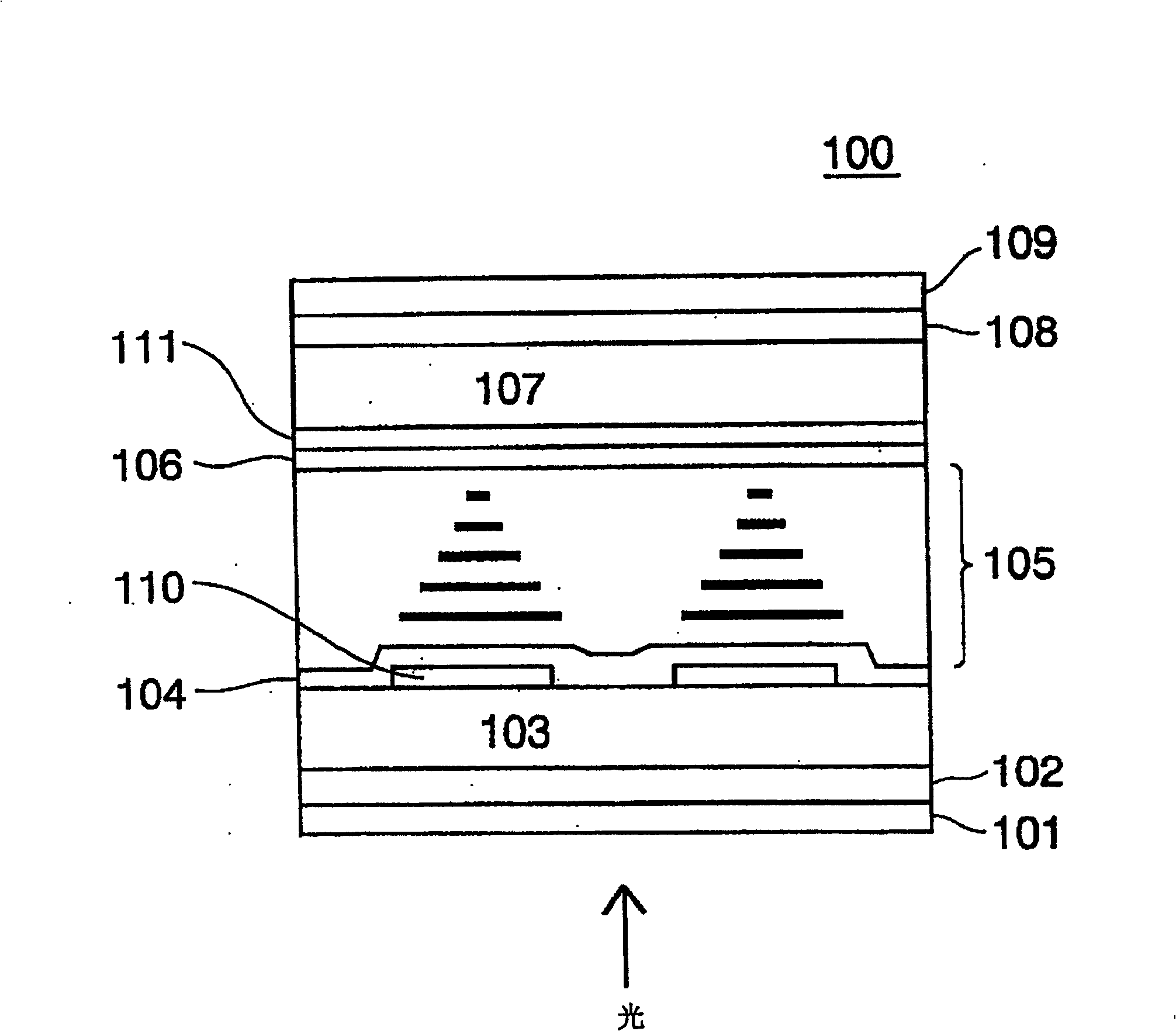
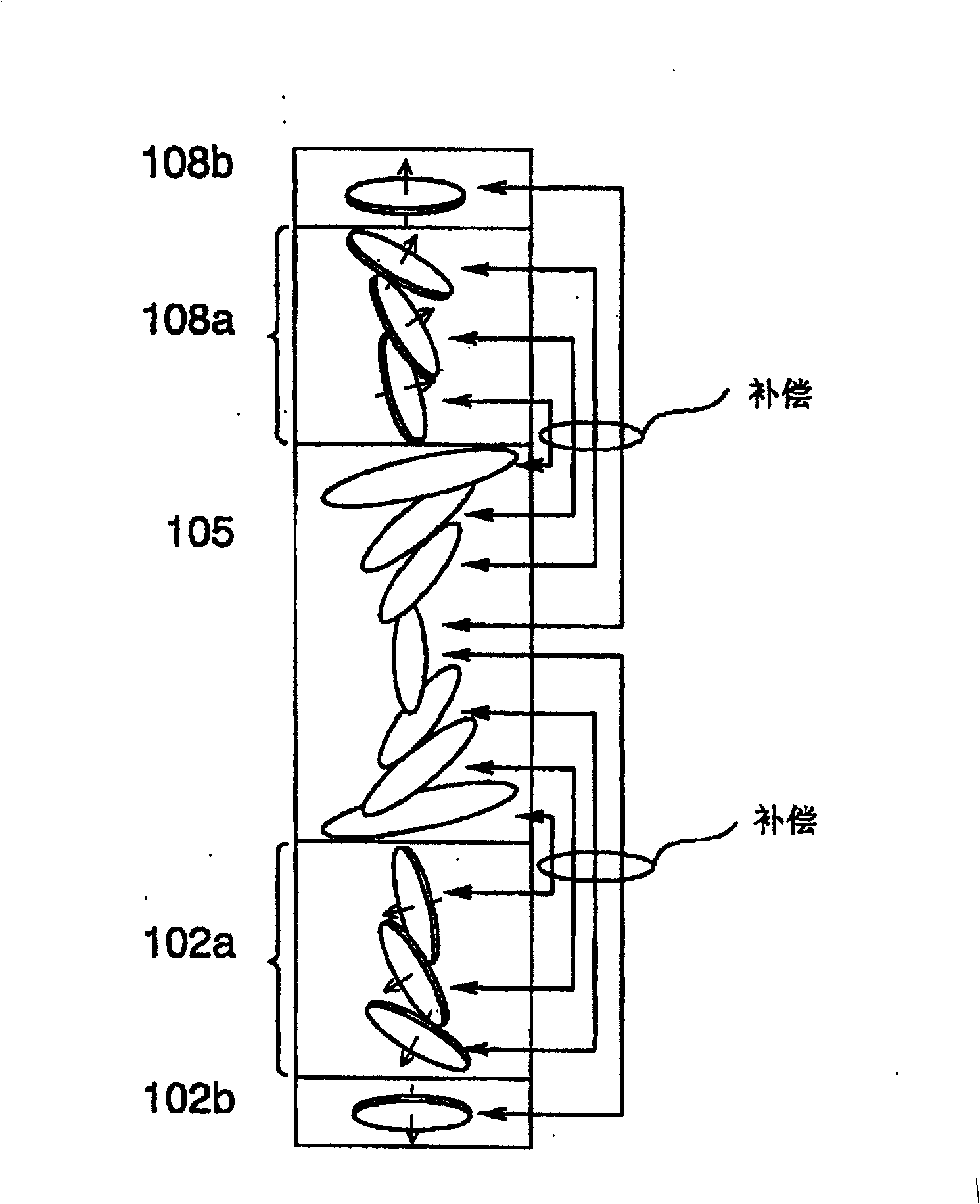
[0038] refer to figure 1 , the LCD device according to the first embodiment of the present invention is generally denoted by 100, which includes a first polarizing film 101, a first compensation film 102, a first glass substrate 103, a first alignment film 104, an LC layer 105, a second alignment The film 106, the second glass substrate 107, the second optical compensation film 108, and the second polarizing film 109 are arranged in this order in the transmission direction of light. The LCD device 100 is of normally white TN mode.

[0039] The first and second polarizing films 101, 109 each have a function of passing light having a specific polarization direction therethrough. The polarization axis of the first polarizing film 101 is perpendicular to the polarization axis of the...


PUM

PropertyMeasurementUnit
angleaaaaaaaaaa
viewing angleaaaaaaaaaa

Abstract

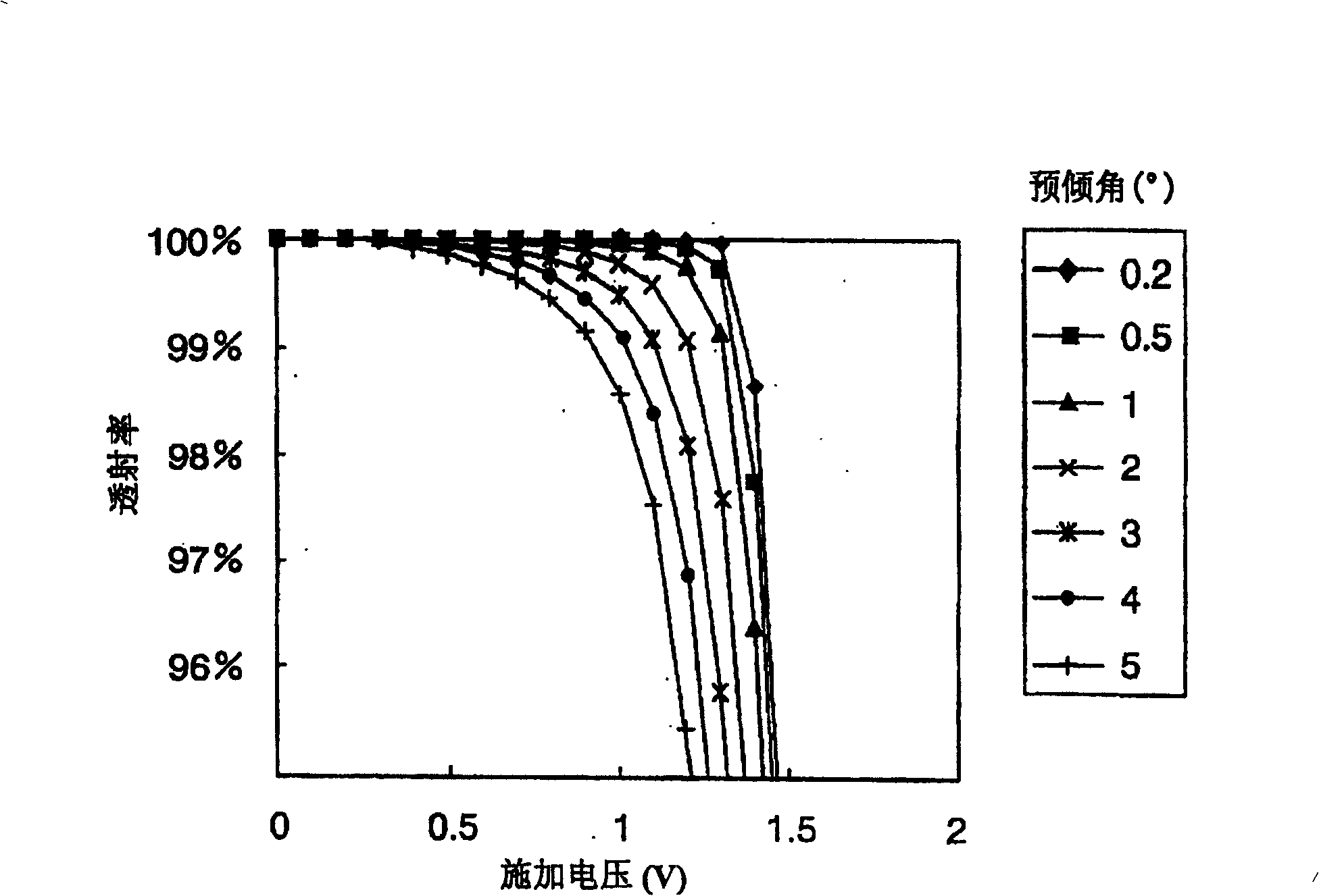
A normally-white twisted-nematic-mode LCD device has first and second optical compensation films for compensating the retardation of an LC layer sandwiched between a pair of substrates. The LC layer is applied with an applied voltage Vw having a relation with respect to the threshold voltage Vth of the LC and a pre-tilt angle theta of the LC layer as follow: Vw<=Vth*exp(-0.235*theta+7.36*10-3). Then visual angle with ideal contrast is increased by using the applied voltage Vw according to the pre-tilt angle theta.

Description

technical field [0001] The present invention relates to a liquid crystal display (LCD) device, and more particularly to a normally white twisted nematic mode (TN mode) LCD device including liquid crystal (LC) molecules having a twist angle of about 90 degrees. Background technique [0002] Generally, a TN mode LC device sequentially includes a first polarizing film, a first glass substrate, an LC layer, a second glass substrate, and a second polarizing film arranged in the following order when viewed from the light incident side. The LC layer includes LC molecules having long axes oriented parallel to the substrate surface when no electric field is applied. From the first substrate to the second substrate, the LC molecules are twisted 90 degrees on their long axis. In a normally white TN mode LCD device, the first and second polarizing films are arranged such that their polarization axes are arranged perpendicular to each other, and thus the LCD device appears white when no...

Claims


Application Information

Patent Timeline
Patent Type & Authority Patents(China)
IPC IPC(8): G02F1/1335
CPCG02F1/133634G02F2203/66G02F1/133632G02F1/1396G02F1/1335
Inventor 佐佐木洋一池野英德
Owner BEIHAI HKC OPTOELECTRONICS TECH CO LTD
Learn More