Polar coordinate converting process for estimating signal background

A technology of polar coordinate transformation and polar coordinate system, applied in the direction of measuring device, measuring electrical variable, digital variable/waveform display, etc., can solve the problem of not considering the difference characteristics of target and background amplitude

Inactive Publication Date: 2009-01-14
TSINGHUA UNIV
View PDF3 Cites 0 Cited by
  • Summary
  • Abstract
  • Description
  • Claims
  • Application Information

AI Technical Summary

Problems solved by technology

However, the previous estimation methods mostly considered the frequency domain characteristics of the signal, but did not consider the amplitude difference characteristics of the target and the background in the space domain

Method used


Image

  • Polar coordinate converting process for estimating signal background
  • Polar coordinate converting process for estimating signal background
  • Polar coordinate converting process for estimating signal background

Examples


Embodiment Construction

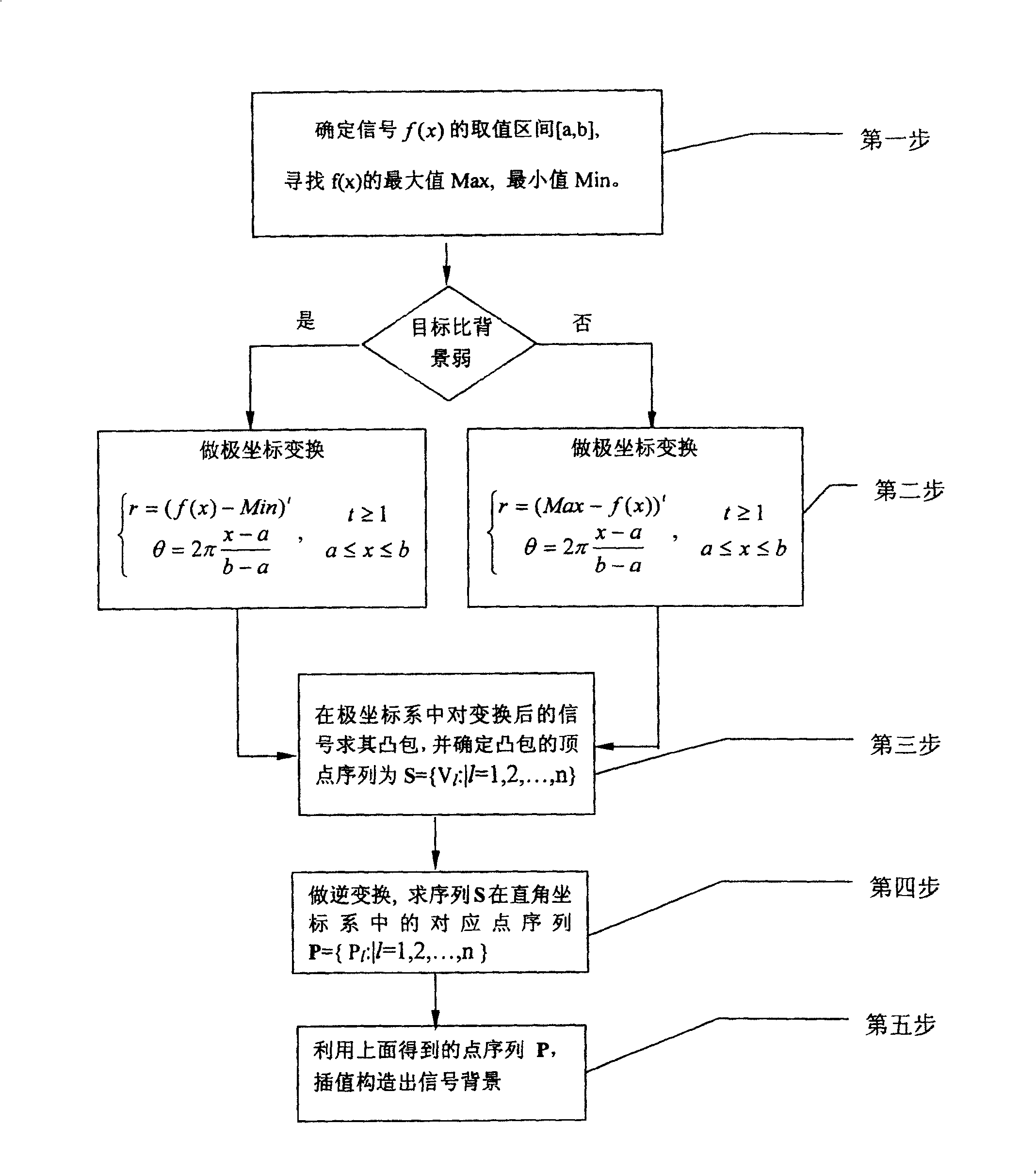
[0035] figure 1 The overall flow chart of the present invention is given, which mainly includes: the first step, determine the value range of the signal, and find the maximum and minimum values ​​of the signal; the second step, do the corresponding polar coordinate transformation according to the strength relationship between the target and the background ; The third step is to find the convex hull and the convex hull vertices of the transformed signal in polar coordinates; the fourth step is to do the inverse transformation, and inversely transform the obtained convex hull vertices into the Cartesian coordinate system; the fifth step is to Based on the inversely transformed points, the signal background is constructed by interpolation method. The specific process is as follows:

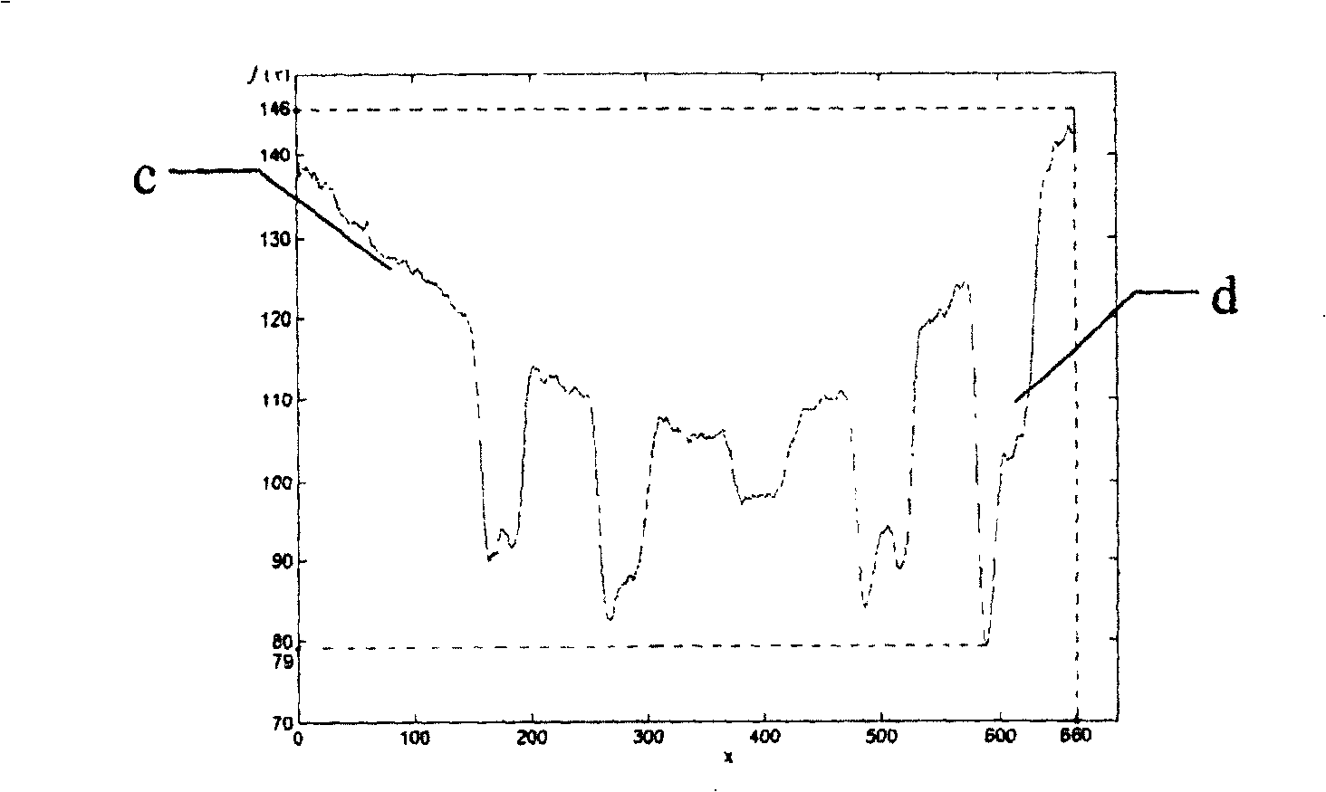
[0036] The first step of the present invention is to determine the value interval [a, b] of the signal f(x), and find the maximum value Max and the minimum value Min of f(x). figure 2 Given a targ...


PUM


Abstract

The present invention belongs to the field of digital signal processing technology and features that the strength difference between the target signal and the background signal is used in back estimation by means of coordinate conversion. The process includes the first polar coordinate conversion according to the strength difference between the target signal and the background signal, the subsequent calculating the convex hull of the converted signal and the inverse conversion of the vertex of the convex hull in the polar coordinate to obtain backgrounds on signal in rectangular coordinate system, and final interpolation to estimate the signal / background ratio by using the background points as the key interpolation points. The process is simple, high in precision and especially suitable for condition with soft target edge and inhomogeneous background.

Description

technical field [0001] The invention belongs to the field of digital signal processing. Background technique [0002] In digital signal processing, the signal we get is often a mixed signal formed by superimposing the target signal on the background signal. In order to find the target signal from the mixed signal, people can first estimate the background signal, then remove the background from the mixed signal, and finally get the target signal. At present, the commonly used background estimation method is the method of designing a signal filter. However, the previous estimation methods mostly considered the frequency domain characteristics of the signal, but did not consider the amplitude difference characteristics of the target and the background in the space domain. The present invention is to perform background estimation on two situations in which the target is stronger than the background or the target is weaker than the background according to the amplitude differen...

Claims


Application Information

Patent Timeline
Patent Type & Authority Patents(China)
IPC IPC(8): G01R13/00G01R23/00
Inventor 张利
Owner TSINGHUA UNIV
Why Eureka
Try Eureka