Photographing device and method for obtaining photographic image having image vibration correction

A technology for photographing devices and images, which is applied to printing devices, measuring devices, image communication, etc., can solve problems such as blurred images, achieve excellent photographic images, and prevent bad photography from occurring.

Inactive Publication Date: 2009-01-14
CANON KK
View PDF7 Cites 0 Cited by
  • Summary
  • Abstract
  • Description
  • Claims
  • Application Information

AI Technical Summary

Problems solved by technology

Thus, there is a possibility that taking multiple exposures for shake correction will inadvertently produce a blurrier image

Method used


Image

  • Photographing device and method for obtaining photographic image having image vibration correction
  • Photographing device and method for obtaining photographic image having image vibration correction
  • Photographing device and method for obtaining photographic image having image vibration correction

Examples


no. 1 example

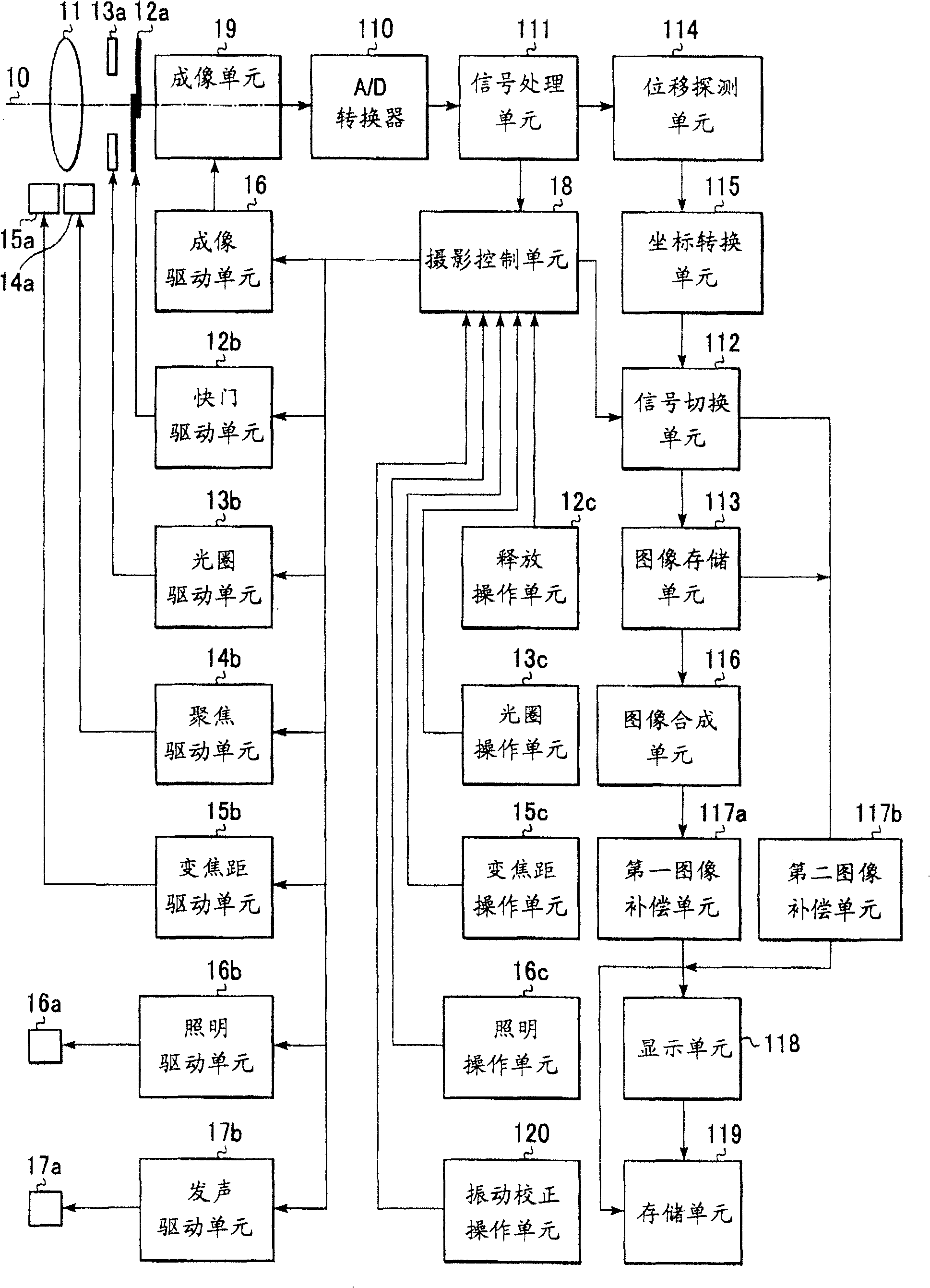
[0045] figure 1 The configuration of the camera (photography device) of the first embodiment of the present invention is shown. The incident luminous flux (photographing light) from the photographing lens 11 is limited by the amount of light passing through the diaphragm 13a, and then undergoes image formation at the imaging unit 19 through the shutter 12a.

[0046] The imaging unit 19 is formed of a semiconductor image sensor such as MOS, CCD, etc., and upon receiving photography light, the imaging unit 19 outputs an electric signal (image signal) corresponding to the light amount. An imaging drive unit 16 drives the imaging unit 19 in accordance with instructions from a photography control unit 18 . Thus, image signals are accumulated and read out by the imaging unit 19 .

[0047] The photographic lens 11 is formed of multiple optical lens groups, and a part or all of these optical lens groups receive driving force from the AF driving motor 14a to move on the optical axis ...

no. 2 example

[0183] The camera according to the second embodiment is a modification of the first embodiment. The camera according to this embodiment is generally the same as that of the first embodiment ( figure 1 ), so the description is made by referring to the same parts with the same reference numerals.

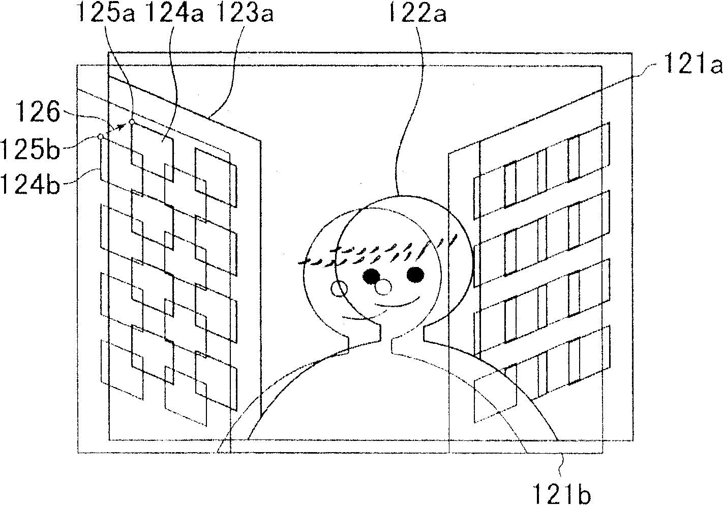
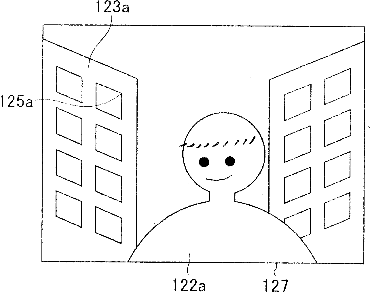
[0184] In the first embodiment, the motion detection unit 114 is used to extract feature points from the central area or peripheral area within the photographing screen before still image photographing (steps #1008 and #1030 in FIG. 5 ).

[0185] On the other hand, the area for extracting feature points is not limited to the above-mentioned area, and the area for extracting feature points before still image shooting can be selected according to the focus area provided in the shooting screen or the area currently in focus.

[0186] This is because the focus area provided in the shooting screen is superimposed on the main subject (person) at the time of still image photography, so feat...

no. 3 example

[0279] Next, a camera according to a third embodiment of the present invention is described. The structure of this camera according to the present embodiment is generally the same as that described in the first embodiment ( figure 1 )same. In the first and second embodiments described above, all the images obtained by multiple exposures are temporarily stored in the image storage unit 113, and then these stored images are used for synthesis, but for the camera according to this embodiment, multiple exposures are performed. exposure while compositing images.

[0280] Figure 8 is a timing diagram illustrating such an action. Note that in this figure, a case is described in which one still image (synthesized image) is obtained from four exposures.

[0281] First, a signal obtained by photoelectric conversion from the first exposure f1 (exposure with illumination light) at the imaging unit 18 is stored there as charges, and then read out as an imaging signal F1. In the same ma...


PUM


Abstract

A photographing device comprises a detecting unit for extracting at least one characteristic point in each image of multiple images and detecting movement of the characteristic point on another image as to a characteristic point on a reference image; a coordinate converting unit for performing coordinates conversion of the other image so as to match the characteristic point on the other image with the characteristic point on the reference image based on the detected results of the detecting unit; a synthesizing unit for synthesizing the reference image and the other image subjected to coordinates conversion by the coordinate converting unit; a determining unit for determining whether or not the characteristic points from the multiple images acquired by the image sensor can be extracted by the detecting unit; and a warning unit for warning users when the determining unit cannot extract characteristic points. A user-friendly photographing device can thus be provided.

Description

technical field [0001] The present invention relates to a photographing apparatus for improving the accuracy of photographed images by correcting image vibrations caused by camera vibrations due to hand movements (hand vibrations), and a method for obtaining photographed images. Background technique [0002] With today's cameras, all important tasks for photography, such as determining exposure time, focus adjustment, etc., are done automatically and the chances of taking a bad photo are greatly reduced, even for users who are not familiar with camera operation. Moreover, recently, a vibration correction system for preventing image vibration caused by camera vibration due to hand movement (hand vibration) has been studied, and almost all factors causing poor photography have been removed. [0003] Now, a brief description will be given regarding a vibration correction system for preventing hand vibration from affecting a photographed picture. [0004] Hand vibration applied...

Claims


Application Information

Patent Timeline
Patent Type & Authority Patents(China)
IPC IPC(8): H04N5/225G03B7/00G03B7/099G03B5/00G03B7/28G03B17/18H04N5/232H04N5/235H04N5/262H04N5/30H04N101/00
CPCH04N5/23254H04N5/2355H04N5/2327H04N5/23277H04N5/235H04N5/2354H04N5/23274H04N5/23248H04N23/68H04N23/6811H04N23/6842H04N23/684H04N23/6845H04N23/70H04N23/741H04N23/74
Inventor 鹫巢晃一
Owner CANON KK
Why Eureka
Try Eureka