Air Flow Sensor and Optional Device That is for Electrical Machine

一种电器设备、空气流的技术,应用在电器设备用选装装置领域,能够解决成本增加等问题,达到简单结构、容易检测、低成本的效果

Active Publication Date: 2016-10-12
KONICA MINOLTA INC
View PDF6 Cites 1 Cited by
  • Summary
  • Abstract
  • Description
  • Claims
  • Application Information

AI Technical Summary

Problems solved by technology

[0005] In order to make an electrical connection between the electrical equipment and the optional device, it is necessary to pre-set an interface (connector, etc.) that can be electrically connected to the optional device on the electrical equipment side, which leads to an increase in cost accordingly

Method used


Image

  • Air Flow Sensor and Optional Device That is for Electrical Machine
  • Air Flow Sensor and Optional Device That is for Electrical Machine
  • Air Flow Sensor and Optional Device That is for Electrical Machine

Examples


Embodiment Construction

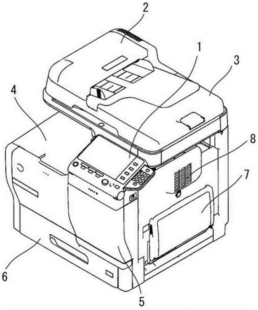
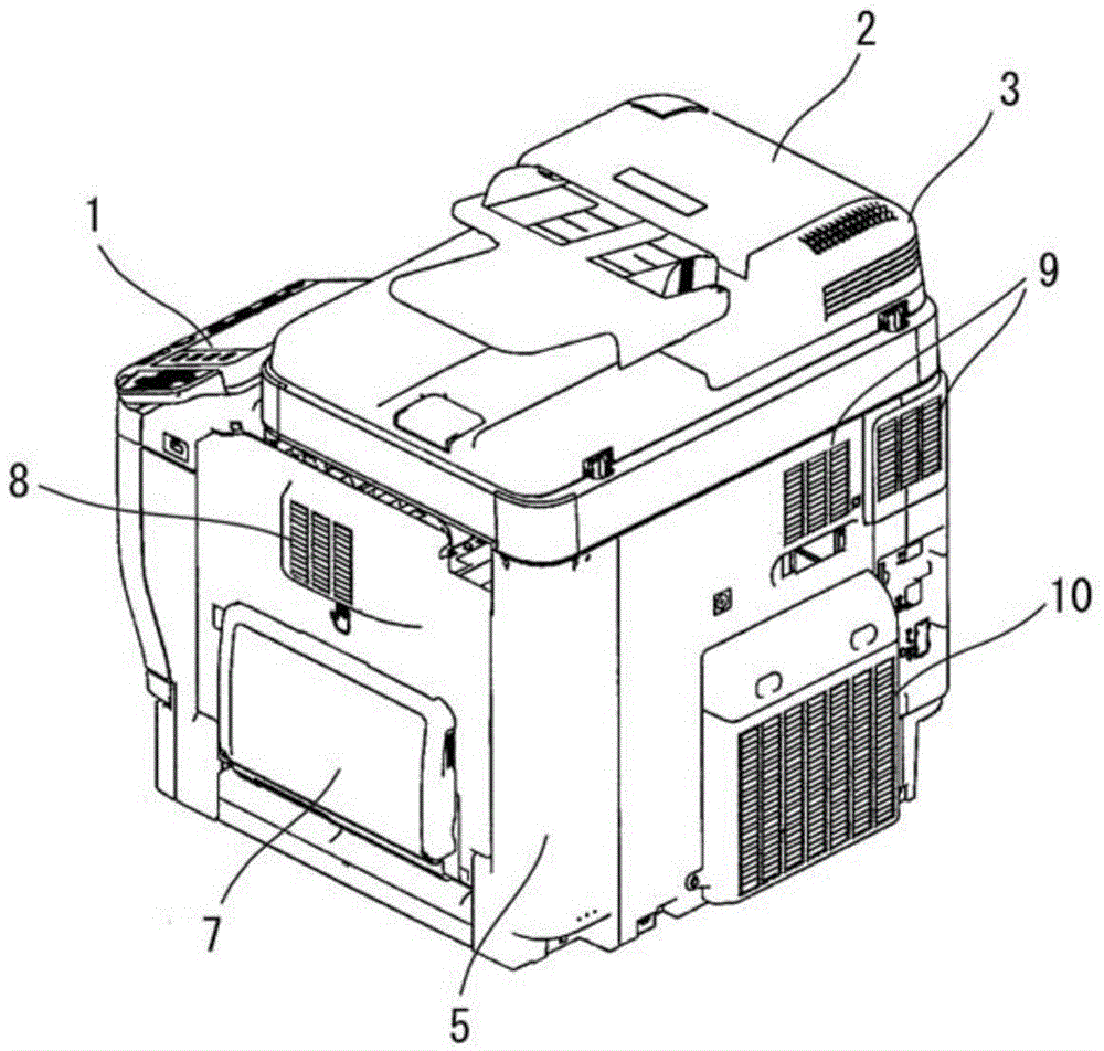
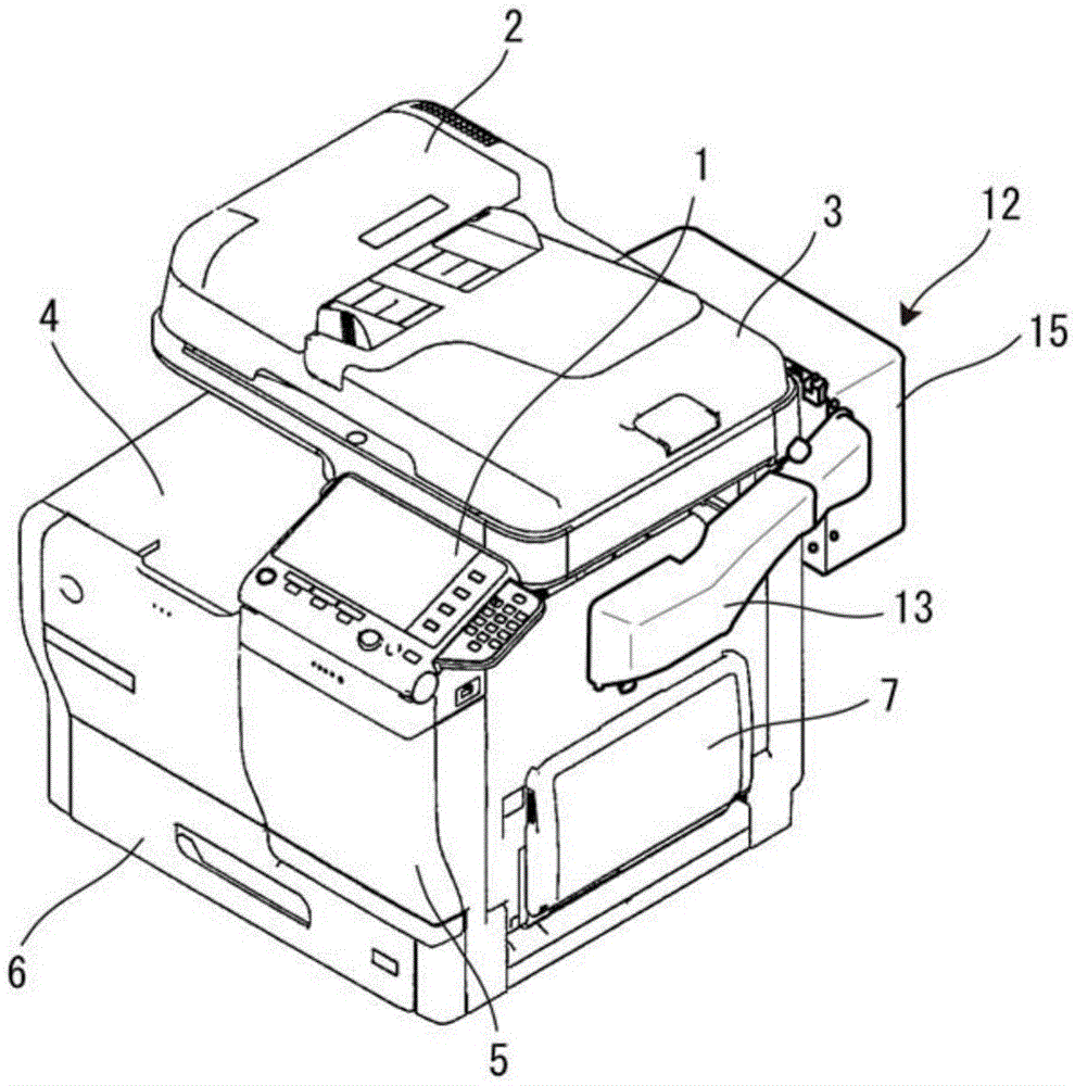
[0067] Hereinafter, embodiments of the present invention will be described based on the drawings. figure 1 and figure 2 It is a perspective view showing a multifunction peripheral as an example of an image forming apparatus to which an optional device according to this embodiment is added. figure 1 It is a perspective view viewed obliquely from the front right of the multifunction device, figure 2 It is a perspective view viewed obliquely from the rear right of the multifunction device. In the following description, when using terms indicating specific directions and positions (such as "left and right", "up and down", etc.) as the benchmark.

[0068] This multifunctional peripheral includes an operation panel 1 including a liquid crystal display on the right side of the front of the main body, and a document reading unit 3 including an automatic document feeder (ADF) 2 is provided on the upper part of the main body. In addition, below the document reading unit 3 and on t...


PUM


Abstract

An air flow sensor includes a case (26), a to-be-detected object (27), and a detector (28). The case includes an intake port (26a) and an exit port (26b) through which air is to flow. The to-be-detected object is located at a first position in the case when the air flowing from the intake port to the exit port has lower than a predetermined level of pressure, and is movable from the first position receiving the air when the air has equal to or higher than the predetermined level of pressure. The detector is disposed outside the case and is configured to detect a movement of the to-be-detected object and output an electrical signal.

Description

technical field [0001] The present invention relates to an air flow sensor for detecting the presence or absence of air flow such as exhaust from electric equipment such as an image forming apparatus, and an optional device for electric equipment including the air flow sensor. Background technique [0002] Exhaust from electrical equipment such as image forming apparatuses contains ultrafine particles (UFP) such as siloxanes generated when silicon is heated or hydrocarbons generated when toner is melted at high temperatures. The constraints on microparticles are becoming increasingly stringent. Therefore, electric equipment is required to discharge air collected and purified by filters or the like from ultrafine particles in the exhaust gas to the atmosphere. Newly developed electrical equipment is designed to meet this restriction. On the other hand, by adding an optional device with the above-mentioned exhaust purification function to existing electrical equipment, it can...

Claims


Application Information

Patent Timeline
Patent Type & Authority Applications(China)
IPC IPC(8): G03G21/20
CPCG03G21/206
Inventor 唐鎌奖畔柳胜己泽野滋川上勋杨树安
Owner KONICA MINOLTA INC
Why Eureka
Try Eureka