

Equipment for reacting sputtering
A technology of equipment and sputtering chamber, which is applied in the field of reactive sputtering equipment and can solve problems such as low sputtering rate
- Summary
- Abstract
- Description
- Claims
- Application Information
AI Technical Summary
Problems solved by technology
Method used
Image

Examples
Embodiment Construction
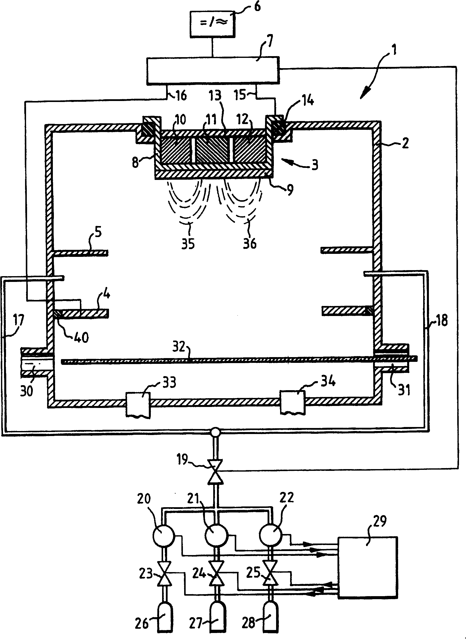
[0028] figure 1 The principle of a sputtering device 1 is shown, which comprises: a sputtering chamber 2 , at least one cathode 3 , an anode 4 , a protective plate 5 , a voltage source 6 and a regulating circuit 7 . The cathode 3 comprises a tubular cathode part 8 to which a target 9 to be sputtered is mounted by means of a flange. Three permanent magnets 10 , 11 , 12 are arranged on the tubular cathode part 8 , and the three permanent magnets 10 , 11 , 12 are connected to each other via a yoke 13 . The cathode part 8 bears on a seal 14 on the edge of the opening in the sputtering chamber 2 . The voltage of the voltage source 6 is conducted via one electrode 15 of the regulating circuit 7 to the cathode part 8 and via its other electrode 16 to the anode 4 . Even if the voltage of the voltage source 6 fluctuates, the regulation circuit 7 keeps the voltage output to the anode-cathode path constant. The fluctuation of the discharge voltage is mainly affected by the conduction ...
PUM
 Abstract
Description
Claims
Application Information