Cutting mechanism of cloth-stentering machine

A cloth stretching machine and cutting head technology, applied in the cutting of textile materials, fabric elongation, fabric surface trimming, etc., can solve problems such as inability to guarantee, poor cloth feeding by the cutting mechanism, and disordered overall rhythm of the stretching machine. To achieve the effect of guaranteeing normalization

Inactive Publication Date: 2009-02-04
常熟市嘉峰机械有限公司
View PDF9 Cites 18 Cited by
  • Summary
  • Abstract
  • Description
  • Claims
  • Application Information

AI Technical Summary

Problems solved by technology

[0003] The applicant found that the cutting mechanism of the above-mentioned structure mainly exposed the following two deficiencies in the actual use process: one is that the sliding cloth plate 12 is not smooth, which is mainly manifested in that it cannot ensure that the cloth head of the new cloth roll is in an effective cloth position. The overall width of the width range is laid on the body of the sliding cloth plate 12 in unison, and the phenomenon of skewing or deviation occurs in light cases, and the sliding cloth fails in severe cases, which affects the smooth progress of the cloth releasing action of the cloth releasing mechanism; It is because the cloth inevitably has static electricity. Once the static electricity appears, it is difficult for the cloth to move down freely along the inclined sliding cloth plate 12, so that the overall rhythm of the spreading machine is disordered, and the probability of stopping and eliminating is high, which affects the working efficiency of the spreading machine.
Therefore, the two major problems of poor cloth feeding and difficult cloth sliding of the cutting mechanism have always plagued cloth stretching machine manufacturers and users of cloth stretching machines. For this reason, the applicant also conducted a literature search, and the retrieved documents are such as CN2552994Y , the name is bevel cutting tension-free automatic stretching machine, but there is no technical inspiration to solve the above problems

Method used


Image

  • Cutting mechanism of cloth-stentering machine
  • Cutting mechanism of cloth-stentering machine
  • Cutting mechanism of cloth-stentering machine

Examples


Embodiment Construction

[0018] Through the applicant's detailed description in combination with the embodiments, it will be more helpful to understand the present invention and make the technical effects brought by the present invention clearer, but the embodiments should not be regarded as limiting the present invention.

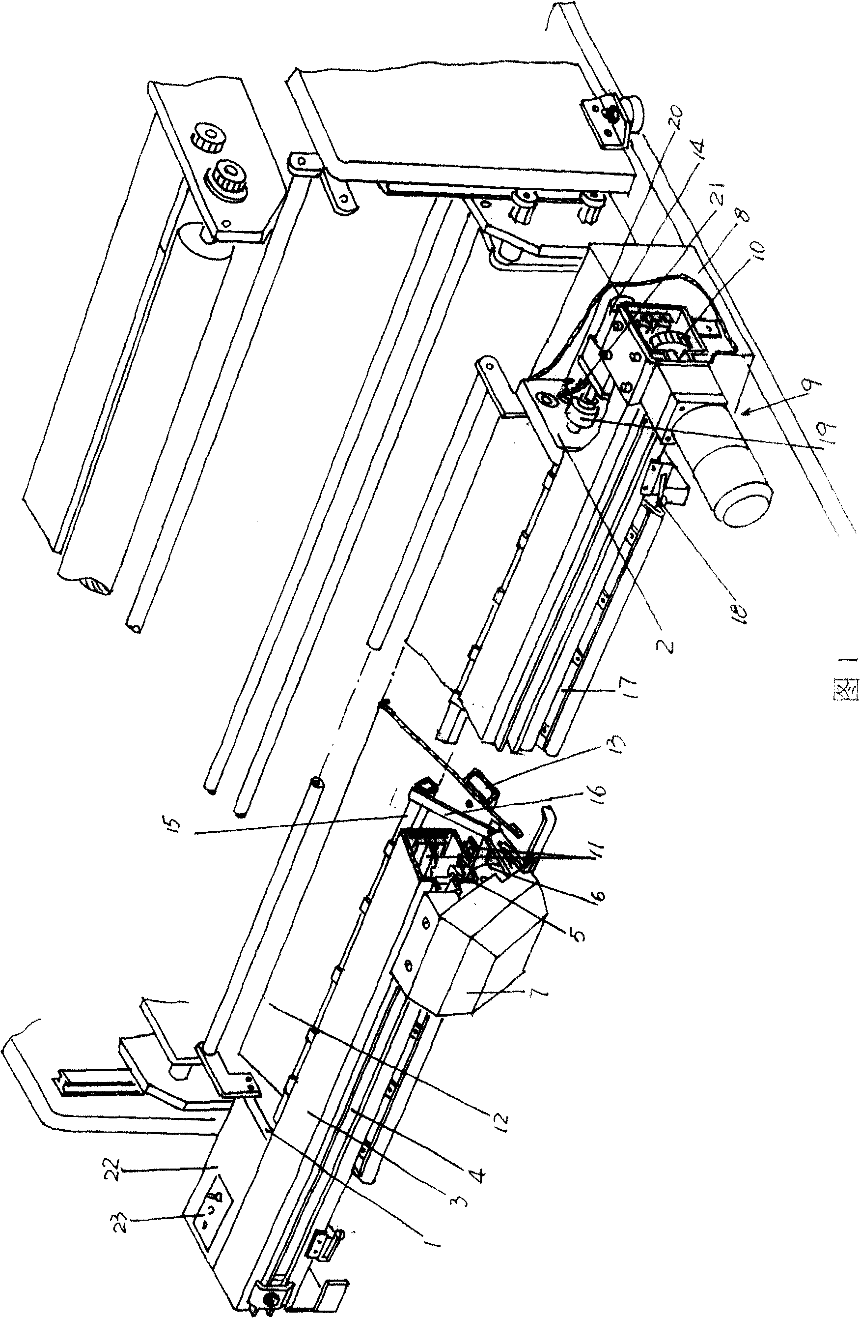
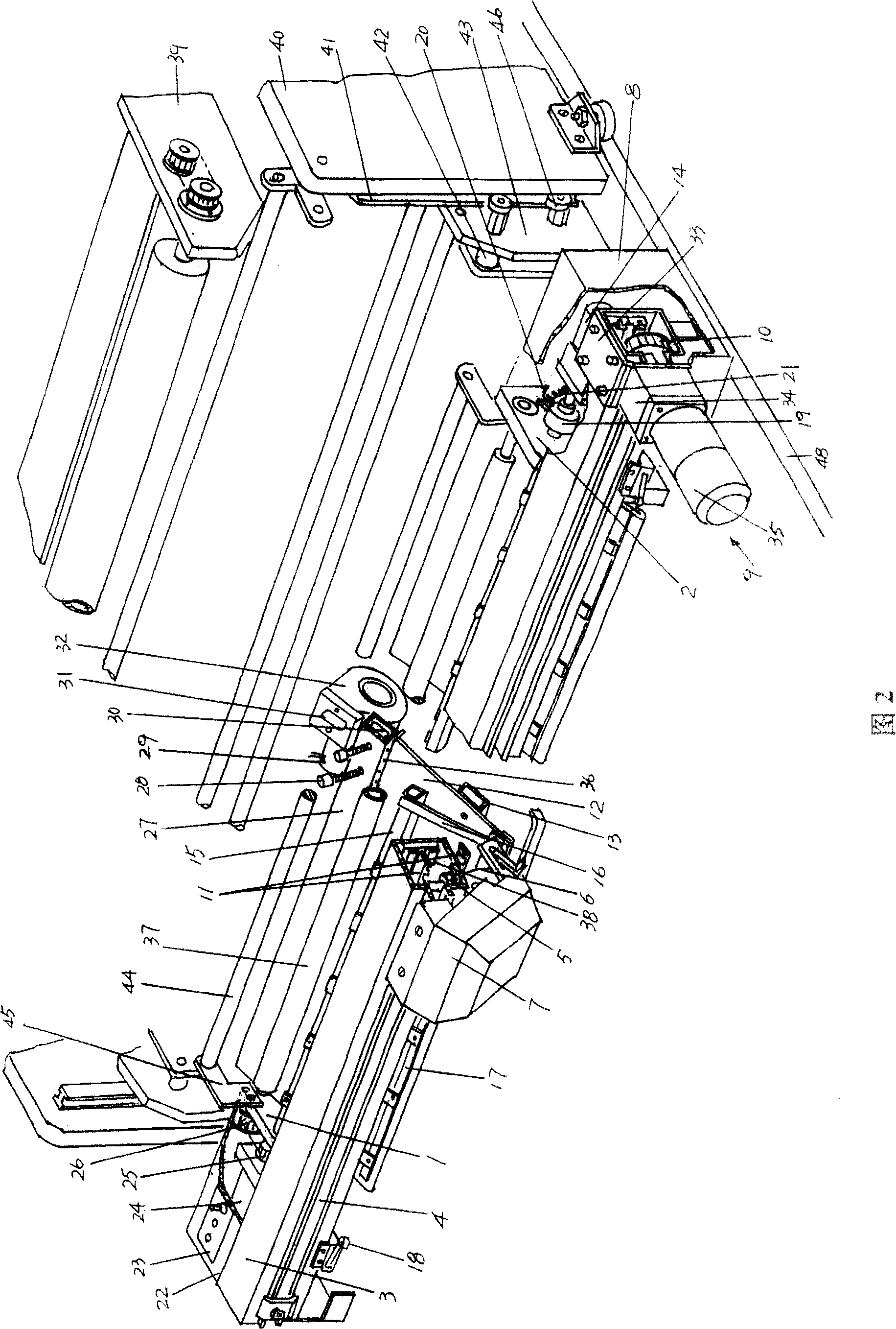
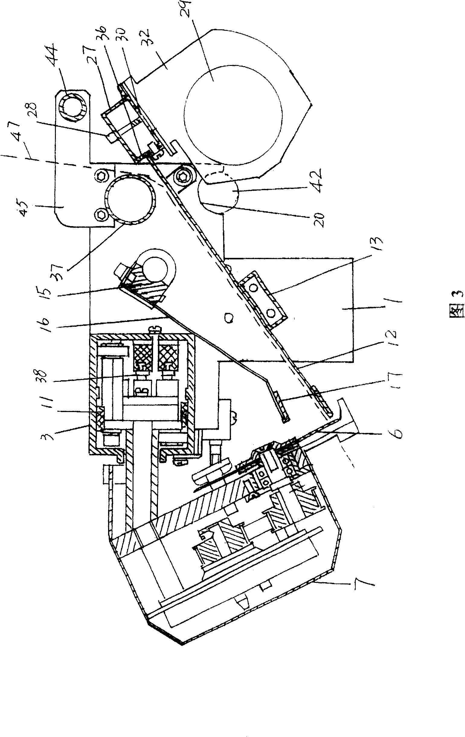
[0019] In Fig. 2 and Fig. 3, a pair of left and right wallboards 1 and 2 of the cutting mechanism of the spreading machine are shown, and the two ends of a guide beam 3 with a rectangular cross-sectional shape are fixed on the left and right wallboards 1 , 2, and the two ends of the guide beam 3 also extend to the left and right casings 22, 8 places, and the two ends of at least one sliding cloth board hosting 13 are welded to the left and right wall panels 1, 2 fastened or riveted or otherwise fixed such as by screws. Taking the position state shown in Figure 2 as an example, a cutting head guide rail 4 is formed on the front side of the guide beam 3. For the cutting head guide r...


PUM


Abstract

The invention relates to a cloth cutting structure of fabric stretcher that includes left wall board, right wall board, nose girder, cloth sliding board, cutting head guide rail, cutting head, synchronous belt driving device, synchronous belt, moment motor, arm pressing axis, a set of pressing arm, hold down strip, a pair of travel switch, spring holder, a pair of pothook, spring and electrical switch, a assistant take-off roller, a wind pipe and air generating device. The using of assistant take-off roller makes the cloth smoothly guide to cloth sliding board, and the using of wind pipe and air generating device make the cloth sliding board form air film that is benefit for the normalization of the running of fabric stretcher.

Description

technical field [0001] The invention relates to a cutting mechanism of a cloth stretching machine, which is arranged on the cloth stretching machine and is used for cutting the fixed-length cloth in the cloth stretching process of the cloth stretching machine, belonging to the technical field of garment machinery. Background technique [0002] The spreading machine is mainly composed of a walking mechanism, a cloth releasing mechanism, a cutting mechanism and an electrical control mechanism such as a programmable logic controller (PLC). The cutting mechanism is hung on the cloth releasing mechanism, and it is responsible for placing the cloth releasing mechanism The function of cloth cutting in the cloth process, and the cloth releasing mechanism is driven by the walking mechanism to move. The cutting mechanism in the prior art is shown in Fig. 1, and it mainly comprises left and right wall panels 1,2, two ends are respectively fixed with left and right wall panels 1,2 guide...

Claims


Application Information

Patent Timeline
Patent Type & Authority Patents(China)
IPC IPC(8): D06H7/00D06C3/00
Inventor 陈元鸣朱晓峰
Owner 常熟市嘉峰机械有限公司
Why Eureka
Try Eureka