Umbilical cord clamps

An umbilical cord clip and clip body technology, which is used in medical science, surgery, obstetrics and gynecology instruments, etc., can solve the problems of not tightening the use effect, unstable performance, and insignificant adjustment effect, and achieves high clamping force and resistance. good effect

Inactive Publication Date: 2009-04-29
何定甫
View PDF7 Cites 0 Cited by
  • Summary
  • Abstract
  • Description
  • Claims
  • Application Information

AI Technical Summary

Problems solved by technology

[0003] Patent No. CN200620107590.9 "Umbilical Cord Clamp" provides an upper and lower clamp body with serrations, which are connected as a whole with locks on the opening ends of the upper and lower clamp bodies. However, this umbilical cord clamp can only There is no adjustment function for clamping. In clinical use, due to the great difference in the size of newborns and the thickness of the umbilical cord, and the umbilical cord itself has sticky, slippery and wet characteristics, some umbilical cords are clamped well, and some are not. Poor use effect and unstable performance
[0004] Patent No. CN200720106459.5 "umbilical cord clamp", although the above patents are improved, the size and arrangement of the serrations on the upper and lower clamps are more reasonable, and two positioning teeth that cooperate with each other are added at the joint of the upper and lower clamps and the adjustment buckle formed by the guide flange, but the adjustment effect is not significant, and the versatility is not enough, so the above two patents cannot be used clinically.

Method used


Image

  • Umbilical cord clamps
  • Umbilical cord clamps
  • Umbilical cord clamps

Examples


Embodiment Construction

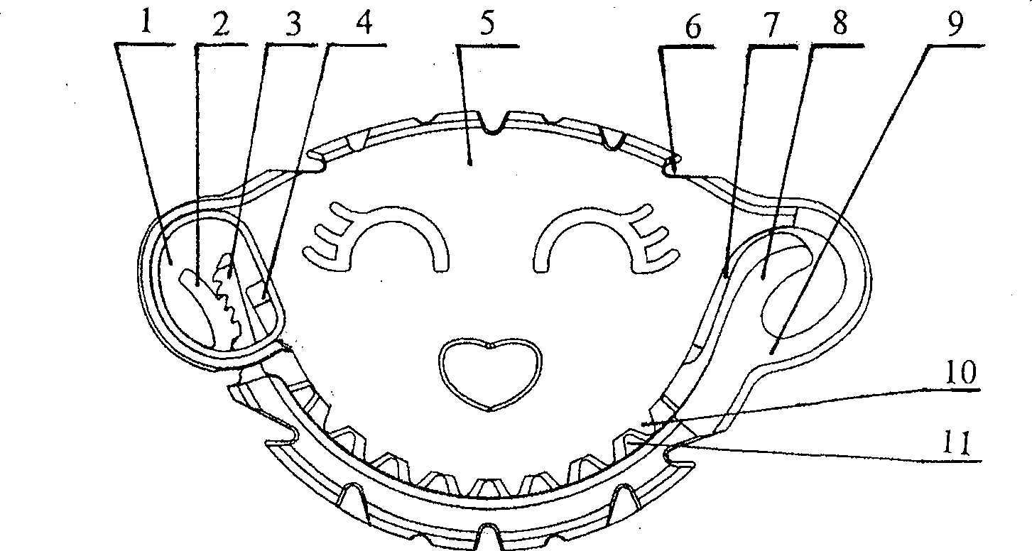
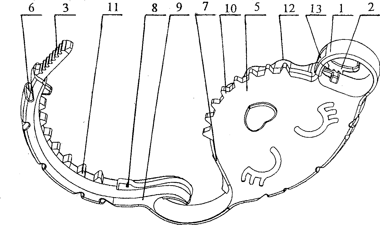
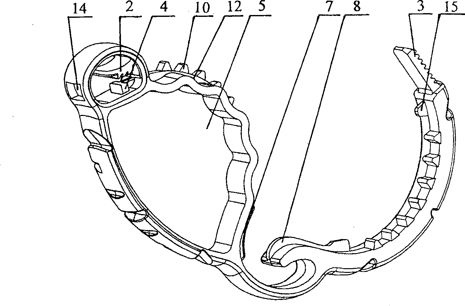
[0012] Embodiments of the present invention will be further described in detail below in conjunction with the accompanying drawings.

[0013] The umbilical cord clamp is composed of an upper clamp body 5 and a lower clamp body 9 butted together. One end of the upper clamp body 5 and the lower clamp body 9 is a conjoined end, and the other end is an open end.

[0014] On the inner surface of the lower clamp body 9, there are evenly distributed, raised, triangular-shaped large sawtooth 11 on the outer edge position. The tooth width of the large sawtooth is about 1 / 2 of the side width of the lower clamp body. There is a long flange 8 at the body, and there are a plurality of connection grooves 6 with different shapes on the outer surface of the upper and lower clamping bodies, which are used for positioning and cooperating with the protrusions on the umbilical cord clipper, such as Figure 4 As shown, the opening end of the lower clip body has a rack 3, the outer surface of the r...


PUM


Abstract

An umbilical cord clamp comprises an upper and lower clamp bodies with the external surfaces provided with connecting grooves and the internal surfaces provided with saw teeth, wherein one ends of the upper and lower clamp bodies are conjoined ends with limit buckles, while the other ends are opening ends; the upper and lower clamp bodies are formed by the integral structure connected by the snapcloses arranged on the opening ends; the snapcloses are adjustable and are formed through connecting the gear rack arranged on the opening end of the lower clamp body and the adjusting buckle arranged inside the locking buckle of the upper clamp body; the limit buckles which are positioned at the conjoined ends of the upper and lower clamp bodies are formed by the staggered long flange fixed on the lower clamp body and the short flange fixed on the upper clamp body. The adjusting buckle with teeth arranged inside the locking buckle and the teeth arranged on the gear rack can be selectively meshed to reach the goal of locking and adjustment; meanwhile, all the big and mall saw teeth and twisting sections of the upper and lower clamp bodies can clamp down and press out umbilical cord, thereby possessing big pressing force and good obstruction effect and being capable of making umbilical cord head of newborn fall off within 24 hours. The invention can be used independently as umbilical cord clamp and also can match with umbilical cord clamp shears during use.

Description

technical field [0001] The invention relates to a medical clamp, in particular to an umbilical cord clamp used for treating the umbilical cord during delivery of newborns. Background technique [0002] After the pregnant woman gives birth and the newborn is born, the umbilical cord that connects the mother and the baby needs to be cut. At this time, the umbilical cord is first clamped with a cord clamp to block the blood, and then the umbilical cord at the junction of the newborn and the mother's placenta is cut off, leaving A part of the umbilical cord in a newborn needs to wait for the umbilical cord to die naturally due to lack of blood flow. [0003] Patent No. CN200620107590.9 "Umbilical Cord Clamp" provides an upper and lower clamp body with serrations, which are connected as a whole with locks on the opening ends of the upper and lower clamp bodies. However, this umbilical cord clamp can only Clamping has no adjustment function. In clinical use, due to the great diff...

Claims


Application Information

Patent Timeline
Patent Type & Authority Patents(China)
IPC IPC(8): A61B17/12A61B17/42
Inventor 何定甫
Owner 何定甫
Why Eureka
Try Eureka