Composition type draw gear of locomotive

A traction device and combined technology, applied in the directions of traction device, transportation and packaging, railway car body parts, etc., can solve the problems of complex structure of intermediate bogie traction device, increased maintenance workload, low adhesion utilization rate, etc. Locomotive maintenance workload and operating costs, reducing maintenance workload and operating costs, and the effect of improving the carrying capacity of the locomotive

Active Publication Date: 2009-05-06
ZHUZHOU ELECTRIC LOCOMOTIVE CO LTD
View PDF10 Cites 1 Cited by
  • Summary
  • Abstract
  • Description
  • Claims
  • Application Information

AI Technical Summary

Problems solved by technology

The traction devices of these locomotives mainly include the following types: Z-shaped low-position diagonal stay rods represented by 6K and SS7 series locomotives. This traction device has a high adhesion utilization rate and good recovery performance of the bogie. , the height of the traction point needs to be adjusted with the wear of the tread, and there are multiple friction pairs in the traction device, which increases the workload of maintenance; the central pin traction device represented by the Myanmar locomotive has a simple structure, but the adhesion utilization rate is low ; Low-centered Z-type pull rods represented by EF500 locomotives, this kind of traction device has good neutrality, but the traction point is high, and the adhesion utilization rate is low; represented by Э П 10, B П 85, and B П 86 The central push-pull low-position single-rod, this kind of traction device has a simple structure, but the adhesion utilization rate is relatively low; the combined traction device represented by the EF200 locomotive, that is, the end bogie is a central push-pull pull rod, and the middle steering The frame adopts Z-shaped low-position diagonal tie rods. This combined traction device has a high adhesion utilization rate, and the intermediate bogie has good reset performance, but the structure of the intermediate bogie traction device is relatively complicated.

Method used


Image

  • Composition type draw gear of locomotive
  • Composition type draw gear of locomotive
  • Composition type draw gear of locomotive

Examples


Embodiment Construction

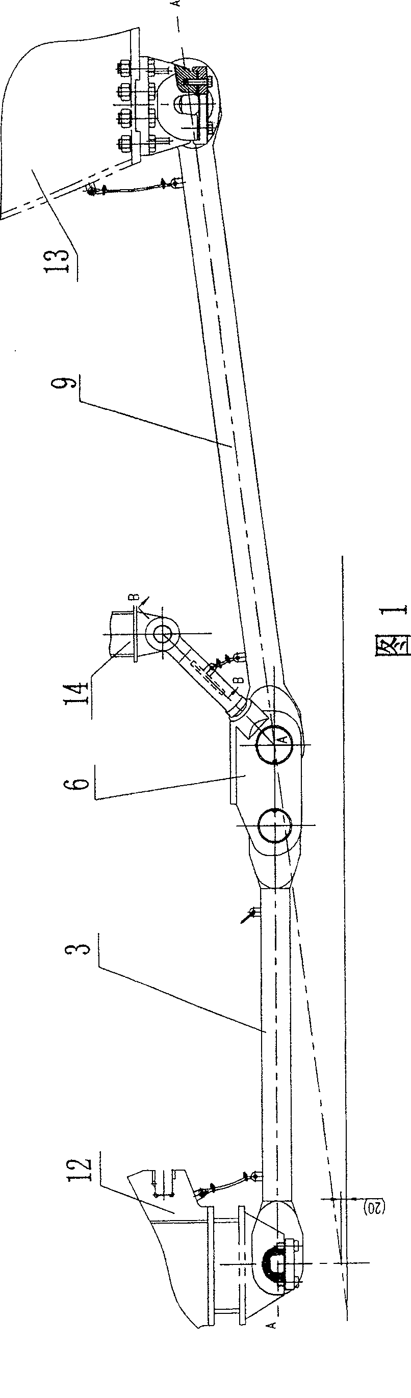
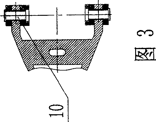
[0013] The accompanying drawings show an embodiment of the present invention, and the present invention will be further described below in conjunction with the accompanying drawings.

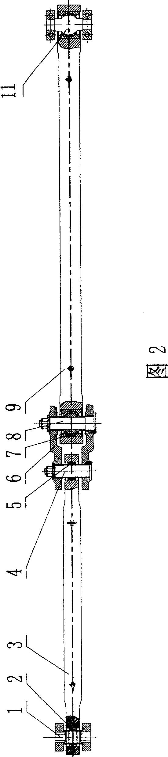
[0014] It can be seen from the accompanying drawings that the present invention is a combined traction device. The traction device of the bogies at both ends and the traction device of the middle bogie adopt different structural forms respectively, wherein the bogies at both ends adopt the central low position Push-pull diagonal tie rods, while the middle bogie adopts a central push-pull flat tie rod; the central low-position push-pull diagonal tie rod structure of the bogies at both ends includes a flat draw bar 3, a triangular brace 6 and an oblique draw bar 9. One end of the flat draw bar 3 links to each other with the frame draw beam 12 by the first draw pin 1, and the other end links to each other with a corner of the triangular brace by the second draw pin 4, and a joint bearing 2 and 5 ar...


PUM


Abstract

A combined towing mechanism for locomotive is composed of the first towing unit for the bogies at both ends and the second towing unit for the middle bogie. The bogie at both ends has a central low-position push-pull oblique pull rod structure consisting of a horizontal towing rod, a triangular supporting rod and an oblique towing rod. The middle bogie has a central push-pull horizontal towing rod structure consisting of a long towing rod and join part.

Description

technical field [0001] The invention relates to a traction device, in particular to a locomotive combined traction device, belonging to locomotive component devices. Background technique [0002] The BO-BO-BO shaft locomotive running part consists of two end bogies and one middle bogie. The traction device mainly transmits the traction and braking force of the locomotive, and at the same time coordinates the relative movement between the bogie and the car body. Domestically, there are mainly 6K locomotives, SS7, SS7B, SS7C, SS7D, narrow-gauge diesel locomotives exported to Myanmar by Dalian Locomotive Works (referred to as Myanmar locomotives), while foreign countries mainly include Japanese EF200 locomotives, EF500 locomotives, Swedish RC locomotives, GM10, Russian Э П 10 electric locomotives and B П 85, B П 86 electric locomotives, etc. The traction devices of these locomotives mainly include the following types: Z-shaped low-position diagonal stay rods represented by 6K...

Claims


Application Information

Patent Timeline
Patent Type & Authority Patents(China)
IPC IPC(8): B61G5/00B61G9/24
Inventor 朱龙驹彭奇彪李冠军张红军伍玉刚黄勇明
Owner ZHUZHOU ELECTRIC LOCOMOTIVE CO LTD
Why Eureka
Try Eureka