Supercharge Your Innovation With Domain-Expert AI Agents!

Surface light source device and light guide used therein

A light guide and surface light source technology, applied in the field of light guides, can solve problems such as insufficient bright line suppression effect, observed bright lines, and insufficient shading, so as to avoid the reduction of incident light, avoid brightness reduction, The effect that does not come off easily

Inactive Publication Date: 2009-06-10
MITSUBISHI RAYON CO LTD
View PDF7 Cites 0 Cited by
  • Summary
  • Abstract
  • Description
  • Claims
  • Application Information

AI Technical Summary

Problems solved by technology

[0014] The method of the above-mentioned Patent Document 4 is a method of adding a light-shielding material to the edge of the light-incident end face of the light guide. Since a part of the light-shielding material is also added to the light-incident end face, part of the incident light on the light-incident end face is blocked. Remember, the amount of light incident from the main light source to the light guide is reduced, and the overall brightness is likely to decrease. At the same time, the incident light near the edge also blocks the light that can be guided without a light-shielding material, so dark lines are prone to occur in the display area. kind of problem
[0015] Moreover, since this method forms a light-shielding material with a very narrow width, it cannot be said that the effect of suppressing the occurrence of bright lines is sufficient.
Moreover, the problem with this method is that it is very difficult to attach the light-shielding material to the edge in practice, and it is also difficult to form the light-shielding material at the desired position, and the light-shielding material attached to the edge is easy to fall off, etc.
[0016] In addition, in the method of the above-mentioned Patent Document 5, a pattern such as a dot pattern is used as a light absorption pattern, but in this case, since there is a region that does not absorb light locally, the light shielding of this region is not sufficient, so there may be observed bright spots. Line and other issues

Method used


Image

  • Surface light source device and light guide used therein
  • Surface light source device and light guide used therein
  • Surface light source device and light guide used therein

Examples


Embodiment 1—9、 comparative example 1

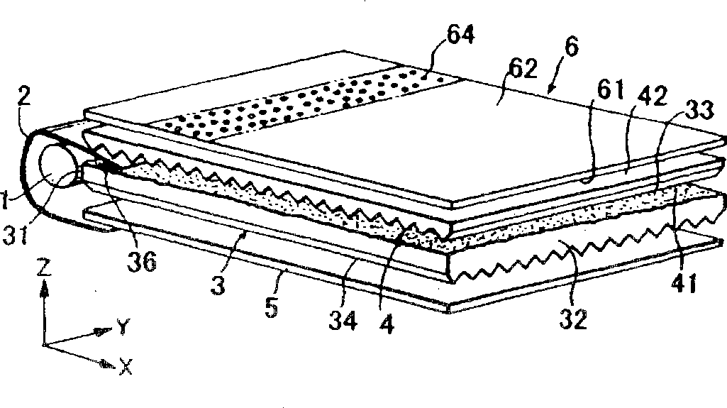
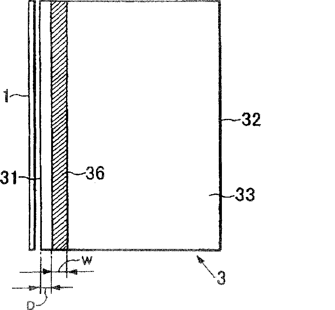
[0141] Using acrylic resin (acrypet [trade name] manufactured by Mitsubishi Rayon Co., Ltd.), one side is rough, and the other side is a prism with a vertex angle of 100°, a radius of curvature of the top tip of 15 microns, and a pitch of 50 microns. The rectangular and wedge-shaped light guide material is a rectangular and wedge-shaped prism pattern in which the prism columns and short sides are continuously arranged in parallel. The portion corresponding to the light-absorbing band was formed by applying the following black ink in various widths from the thicker long side to the rough surface of the light guide material forming the prism pattern by screen printing. In addition, when black ink was printed on a transparent acrylic plate with a thickness of 2 mm in a size capable of measuring visible light transmittance by the same method, the visible light transmittance of the ultraviolet curable black ink was 40%.

[0142] Black ink:

[0143] Acrylic oligomer: 45% by weight ...

Embodiment 1—800

[0150] Example 1—800 microns

Embodiment 2—700

[0151] Example 2—700 microns


PUM

PropertyMeasurementUnit
heightaaaaaaaaaa
diameteraaaaaaaaaa
angleaaaaaaaaaa

Abstract

A planar light source device capable of preventing the occurrence of a luminescent line in the vicinity of a light incident end face without interrupting an incident light incoming from a primary light source and entering at a light incident end face, and being not likely to cause a decrease in incident light quantity, that is, without lowering entire luminance and producing dark lines to be caused when light to be originally guided is shaded. A platy light guide ( 3 ) that guides light emitted from a primary light source ( 1 ) and has a light incident end face ( 31 ) for receiving light from the primary light source ( 1 ) and a light emitting face ( 33 ) for outputting the guided light which is formed with a light absorption zone ( 36 ) extending along the light incident end face ( 31 ) and having a width of 50 to 1000 mum, and a side edge closer to the light incident end face ( 31 ) of the light absorption zone ( 36 ) is up to 300 mum away from the light incident end face ( 31 ). The light incident end face ( 31 ) is so constructed that light emitted from the primary light source ( 1 ) is incident as far as the boundary with the light emitting face ( 33 ).

Description

technical field [0001] The present invention relates to an edge-illuminated surface light source device and a light guide used therein, and specifically relates to a light-incident end face of the light guide facing the main light source, which can be used as a rib-shaped bright line and along the light-incident end face. A surface light source device with reduced brightness distribution unevenness in dark line observation, a dedicated light guide therefor, and a manufacturing method thereof. [0002] The surface light source device of the present invention is suitable for backlighting of liquid crystal display devices, for example. Background technique [0003] In recent years, liquid crystal display devices have been used as monitors for notebook PCs and the like, as display units for liquid crystal televisions, liquid crystal televisions with video playback, and the like, and have been widely used in various other fields. A liquid crystal display device can basically be ...

Claims


Application Information

Patent Timeline
Patent Type & Authority Patents(China)
IPC IPC(8): G02F1/13357F21V8/00F21Y103/00G02B6/00F21Y105/00
Inventor 山下友义村山义明野崎义人
Owner MITSUBISHI RAYON CO LTD
Features
  • R&D
  • Intellectual Property
  • Life Sciences
  • Materials
  • Tech Scout
  • Unparalleled Data Quality
  • Higher Quality Content
  • 60% Fewer Hallucinations
Learn More