Supercharge Your Innovation With Domain-Expert AI Agents!

Devices and methods for controlling time sequences for displays

A technology for controlling displays and display devices, applied to static indicators, instruments, etc., can solve problems such as uneven display

Inactive Publication Date: 2009-06-24
TPO DISPLAY
View PDF3 Cites 0 Cited by
  • Summary
  • Abstract
  • Description
  • Claims
  • Application Information

AI Technical Summary

Problems solved by technology

Unfortunately, even when displaying a solid color, differentially coupled charges between subpixels of the same color (e.g., 216r and 218r) can make the display non-uniform

Method used


Image

  • Devices and methods for controlling time sequences for displays
  • Devices and methods for controlling time sequences for displays
  • Devices and methods for controlling time sequences for displays

Examples


Embodiment Construction

[0046] The invention will be more fully described hereinafter with reference to the accompanying drawings. This invention may, however, be embodied in many different forms and should not be construed as limited to the embodiments set forth herein. Furthermore, like element numbers refer to like elements throughout.

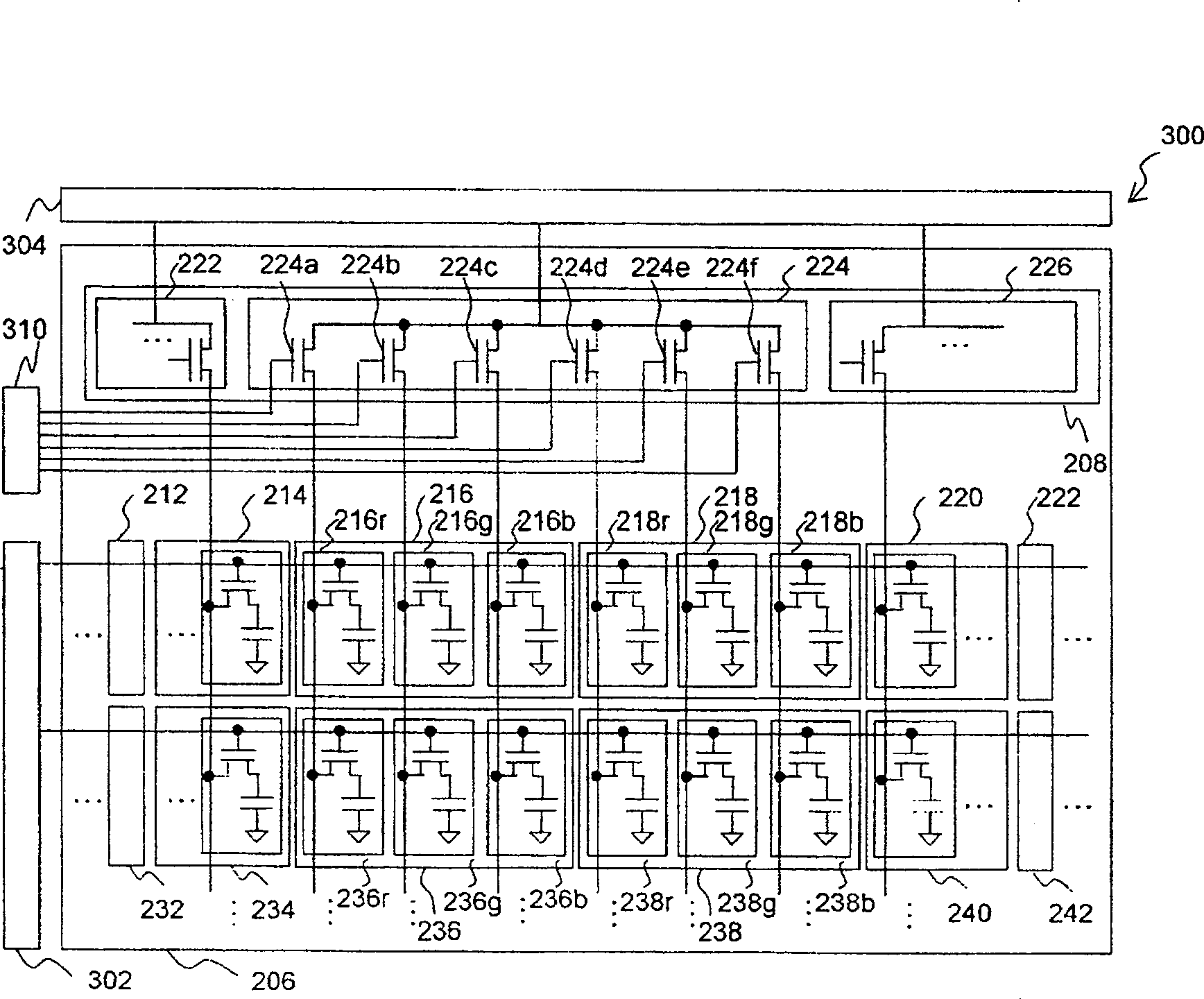
[0047] see Figure 3A , which is a schematic diagram of a liquid crystal display device according to an embodiment of the present invention. In this embodiment, the liquid crystal display device 300 includes a control device 310 that operates in a driving method different from that of the LCD device 200, a corresponding gate driver device 302, a source driver device 304, and a figure 2 The display region 206 shown in FIG. 10 has the same pixel architecture as the display region 206 . Through the driving method described below, the liquid crystal display device 300 can improve its image uniformity.

[0048] Figure 3B as well as Figure 3C It is a timing diagr...


PUM


Abstract

The present invention provides a method for controlling a display panel, wherein the display panel includes a plurality of pixels, and wherein each pixel of the plurality of pixels includes a plurality of sub-pixels. Representative methods include: controlling the timing to turn on pixels to achieve at least one of the following: the average influence of the coupling of each sub-pixel in two consecutive time frames is the same; and two adjacent columns of sub-pixels The average influence of the coupling of the upper two sub-pixels is the same.

Description

technical field [0001] The invention relates to the control of pixels of a display device. Background technique [0002] figure 1 is a schematic diagram of a known liquid crystal display (LCD). Such as figure 1 As shown in , a known LCD panel 100 generally includes a gate driver 102 , a source driver 104 and a display area 106 . The display area 106 includes a pixel array composed of a plurality of pixels. For example, a known display area with a resolution of 1024x768 has 1024 rows and 768 columns of pixels, such as figure 1 Pixels 112, 114, 116, 122, 124, 126, etc. are shown in . In addition, each pixel has a red sub-pixel, a green sub-pixel and a blue sub-pixel. For example, the pixel 112 in the first column and the first row of the display area 106 has a red sub-pixel 112r, a green sub-pixel 112g, and a blue sub-pixel 112b. Therefore, the display area 106 has 3072 rows and 768 columns of sub-pixels. [0003] exist figure 1 In the present invention, each sub-pixe...

Claims


Application Information

Patent Timeline
Patent Type & Authority Patents(China)
IPC IPC(8): G09G3/36G09G3/20G02F1/133
CPCG09G2320/0209G09G2310/0297G09G3/3688
Inventor 庄晴云赖宠文李思贤张富智奥规夫庄立圣邓文杰
Owner TPO DISPLAY
Features
  • R&D
  • Intellectual Property
  • Life Sciences
  • Materials
  • Tech Scout
  • Unparalleled Data Quality
  • Higher Quality Content
  • 60% Fewer Hallucinations
Learn More