Imaging cartridge, and assembling method and disassembling method thereof
A technology of imaging and cartridges, applied in electrography, optics, instruments, etc., can solve problems such as reducing recycling efficiency
- Summary
- Abstract
- Description
- Claims
- Application Information
AI Technical Summary
Problems solved by technology
Method used
Image
Examples
no. 1 approach
[0075] A preferred embodiment of the present invention will be described below with reference to the accompanying drawings.
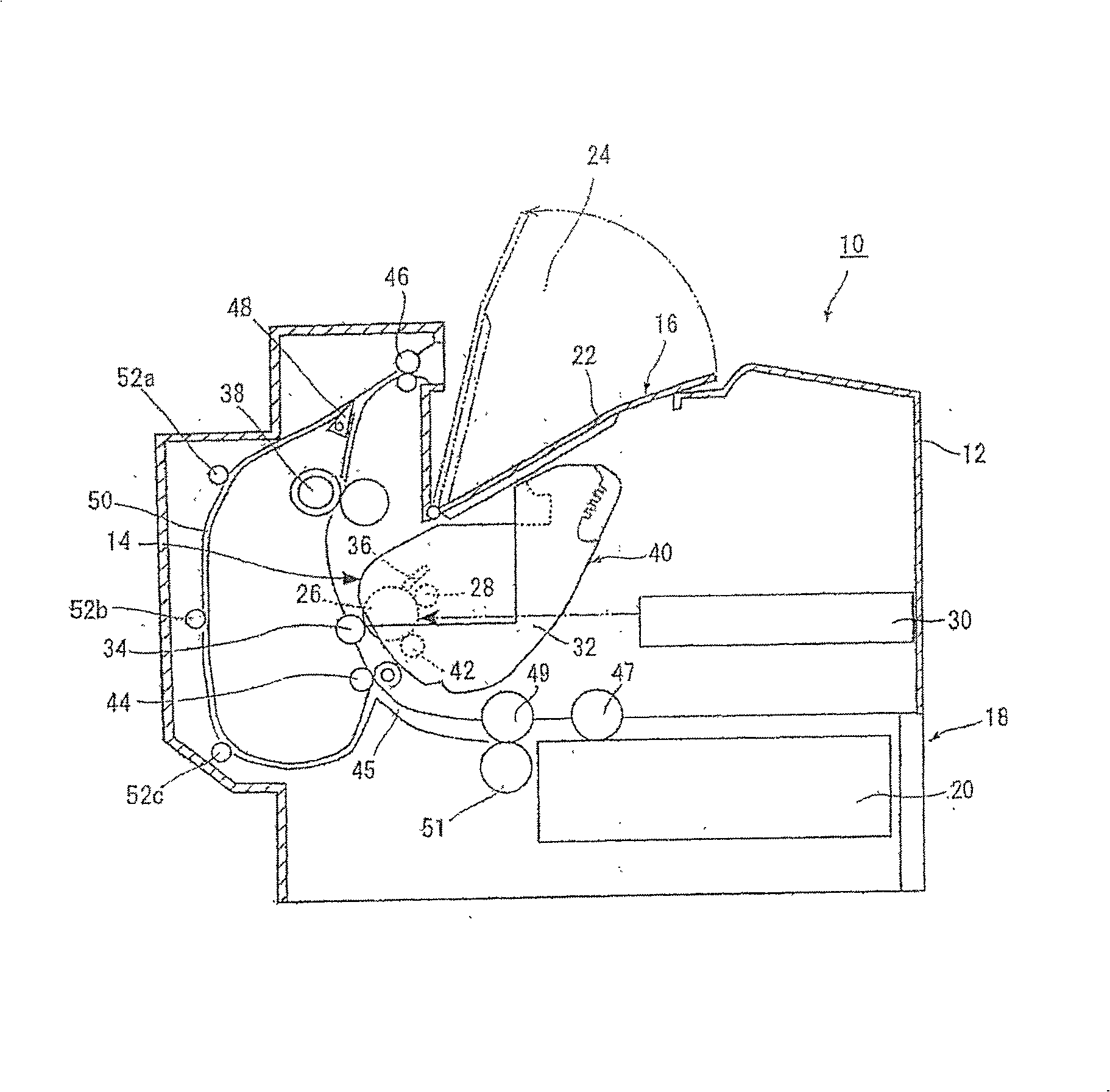
[0076] figure 1The outline of the image forming apparatus 10 according to the embodiment of the present invention is shown. The image forming apparatus 10 includes an image forming apparatus body 12 . An image forming device 14 is installed in this image forming apparatus main body 12 . The delivery unit 16 is installed on top of the image forming apparatus main body 12 . A sheet feeder 18 is installed at a lower portion of the image forming apparatus main body 12 .
[0077] The delivery portion 16 has an inclined portion 22 that is rotatable around the image forming apparatus body 12 . The inclined portion 22 whose output side is located at a low place gradually rises toward the front ( figure 1 center to the right). The inclined portion 22 has the output side as its bottom end and the raised front end as its top end. The inclined portion 22 i...
no. 2 approach
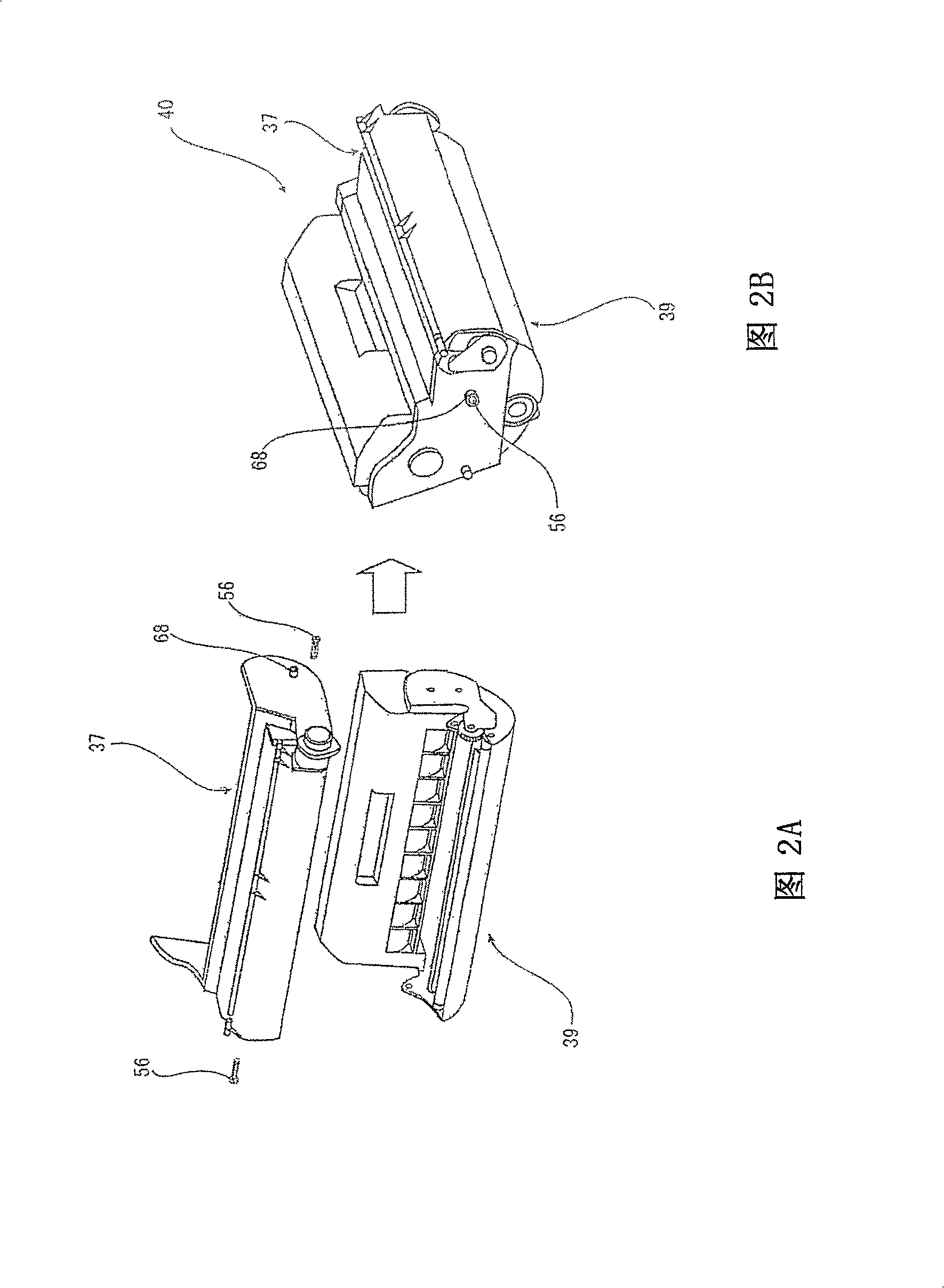
[0162] An imaging cartridge, and its assembly and disassembly method, including the structure in the first embodiment, in Figure 1 to Figure 3 0 has been explained. Therefore, details are not described in this embodiment.
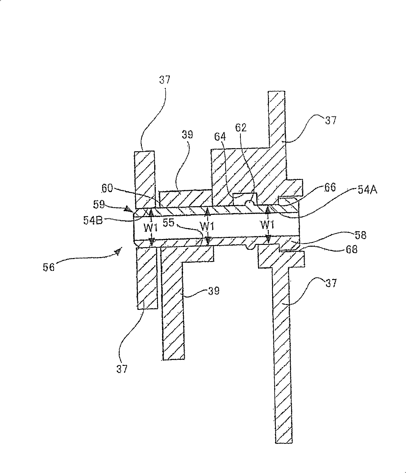
[0163] Figure 31 It is a cross-sectional view showing the overall components of the joint part of the imaging cartridge 40, wherein the first case 37 and the second case 39 are combined through the connecting pin 56 in the embodiment. Figure 31 It shows that the first casing 37 and the second casing 39 are combined with each other by means of the connecting pin 56 so that a part of the second casing 39 is inserted between the two parts of the first casing 37 from both sides. The second insertion hole 55 of the second case 39 is arranged between the first insertion holes 54A and 54B of the first case 37 . In this case, the first insertion holes 54A and 54B, and the second insertion hole 55 have the same inner diameter W1.
[0164] The connection pin 5...
PUM
 Abstract
Description
Claims
Application Information
 - R&D
- Intellectual Property
- Life Sciences
- Materials
- Tech Scout
- Unparalleled Data Quality
- Higher Quality Content
- 60% Fewer Hallucinations
Browse by: Latest US Patents, China's latest patents, Technical Efficacy Thesaurus, Application Domain, Technology Topic, Popular Technical Reports.
© 2025 PatSnap. All rights reserved.Legal|Privacy policy|Modern Slavery Act Transparency Statement|Sitemap|About US| Contact US: help@patsnap.com


