
Converter

A converter and filter technology, applied in the field of converters, can solve the problems of not increasing the switching frequency, increasing the size of the device, and increasing the cost, and achieves the effects of improving the control response speed, providing DC power, and suppressing transient voltage fluctuations.

Inactive Publication Date: 2009-07-22
MITSUBISHI ELECTRIC CORP
View PDF4 Cites 0 Cited by
  • Summary
  • Abstract
  • Description
  • Claims
  • Application Information

AI Technical Summary

Problems solved by technology

[0005] With the conventional method, for instantaneous voltage fluctuations, it is necessary to increase the switching frequency to increase the control response speed, or to increase the capacitance of the smoothing capacitor to alleviate the influence of voltage fluctuations, or to add hardware for overvoltage prevention, and to deal with this. If the high-precision standard is used, there is a problem of increasing the size of the device and increasing the cost
[0006] The present invention is proposed to solve related problems, and the purpose is to obtain a converter, which can not increase the switching frequency, and will not be damaged due to the increase of the capacitance of the smoothing capacitor and the addition of hardware for preventing overvoltage. Causes an increase in device size and cost, can suppress instantaneous voltage fluctuations, and can output desired DC power with high precision

Method used


Image

  • Converter
  • Converter
  • Converter

Examples


Embodiment Construction

[0013] Embodiment 1

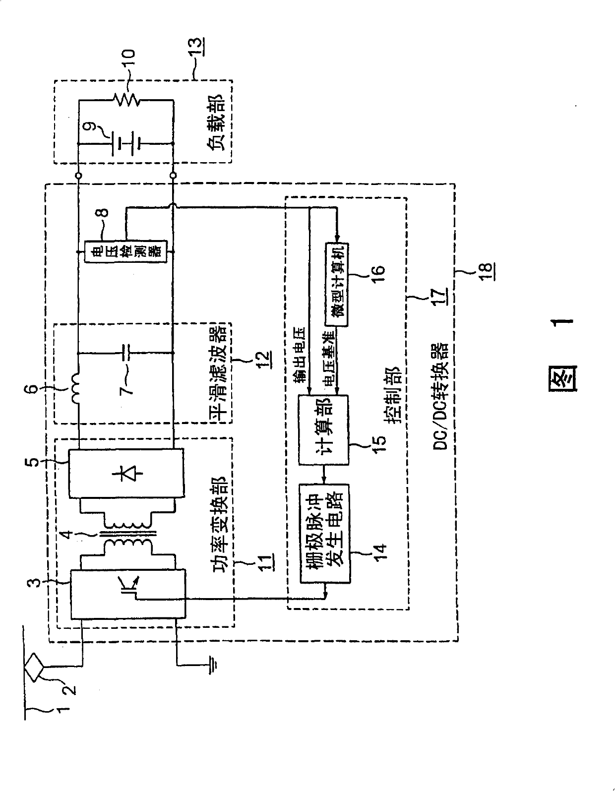
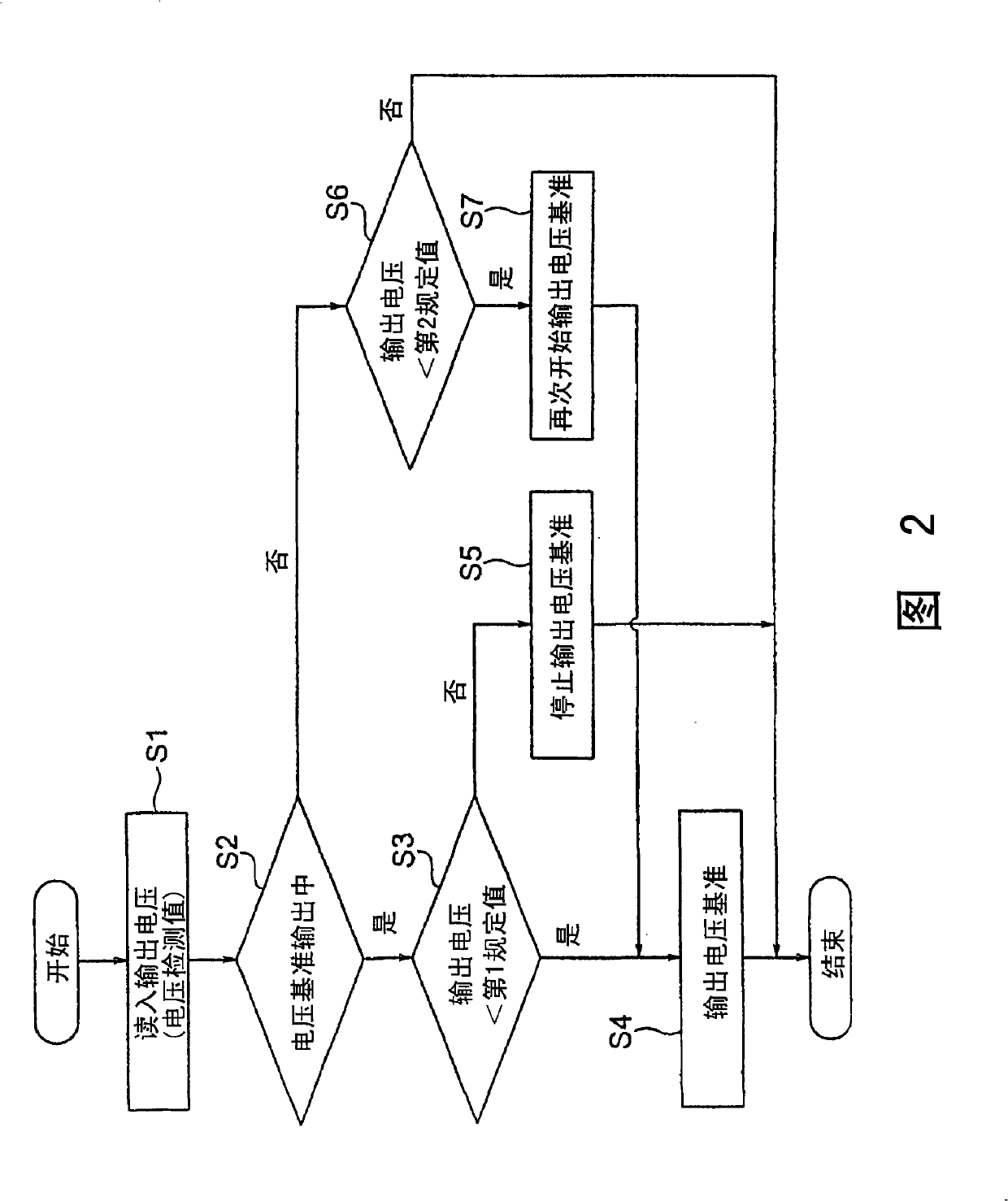
[0014] Fig. 1 is a diagram showing the structure of a converter in Embodiment 1 of the present invention. The example in FIG. 1 is an example in which the converter of the present invention is used in a DC / DC converter for an electric vehicle, and FIG. 2 is a flowchart showing the operation of a microcomputer provided in the converter.

[0015] In FIG. 1 , DC / DC converter 18 is composed of voltage detector 8 , power conversion unit 11 , smoothing filter 12 , and control unit 17 . The DC / DC converter 18 is a device that performs DC / DC conversion on the DC power obtained from the overhead line 1 through the pantograph 2 and supplies the DC power to the load unit 13 composed of the battery load 9 and the electric load 10 .

[0016] The power conversion unit 11 is composed of an inverter 3 , a transformer 4 , and a rectifier 5 . The switching elements of the inverter 3 are composed of, for example, IGBTs, controlled by gate pulses from the control unit 17, ...


PUM


Abstract

It is possible to provide a converter capable of suppressing an instantaneous voltage fluctuation and outputting a desired DC power of high accuracy. The converter includes a power conversion unit (11) performing power conversion of power supplied, a smoothing filter (12) for smoothing the power electrically converted, a voltage detector (8) for detecting voltage of the power smoothed, and a control unit (17) for outputting a pulse signal for controlling the switching element flow ratio in the power conversion unit (11) so that the output voltage from the voltage detector (8) has a desired voltage value. The control unit (17) temporarily stops power supply when the output voltage has increased to a first predetermined voltage so that the output voltage from the voltage detector (8) does not become an excessive voltage exceeding a desired voltage value and resumes power supply when the output voltage has been lowered to a second predetermined voltage so that the output voltage from the voltage detector (8) does not become a voltage lower than the desired voltage value.

Description

technical field [0001] The present invention relates to a converter, and more particularly to a DC / DC converter or an AC / DC converter that prevents instantaneous voltage fluctuations in the output voltage by temporarily stopping and restarting power conversion, and supplies a desired DC voltage to the output side device. Background technique [0002] In the system configuration of conventional DC / DC converters for electric vehicles, the output voltage reference generated from the microcomputer is compared with the output voltage detection value, and the conduction rate of the switching element is controlled so that the output voltage matches the voltage reference ( For example, refer to Non-Patent Document 1). [0003] The allowable variation range of the domestically oriented output voltage standard described in the above-mentioned Non-Patent Document 1 is within ±10%. Generally, the range of voltage variation in foreign standards is only allowed to be about ±1%. If compa...

Claims


Application Information

Patent Timeline
Patent Type & Authority Patents(China)
IPC IPC(8): H02M3/155
CPCB60L9/005Y02T10/725B60L2210/20H02M3/33507H02M1/36Y02T10/72H02M3/155H02M3/28
Inventor 楠林千代
Owner MITSUBISHI ELECTRIC CORP
Learn More