
Vibration controller for active vibration insulators and method for controlling vibrations for the same

Active Publication Date: 2005-08-25
TOKAI RUBBER IND LTD
View PDF8 Cites 8 Cited by
  • Summary
  • Abstract
  • Description
  • Claims
  • Application Information

AI Technical Summary

Benefits of technology

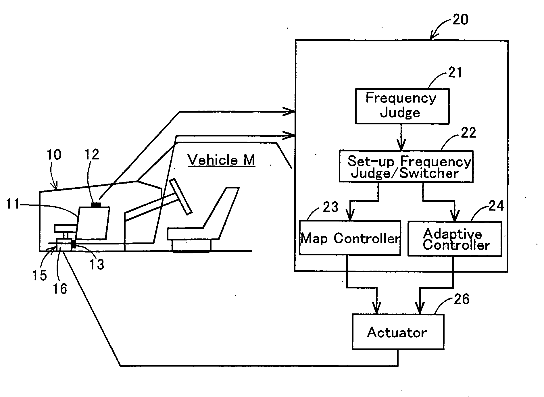
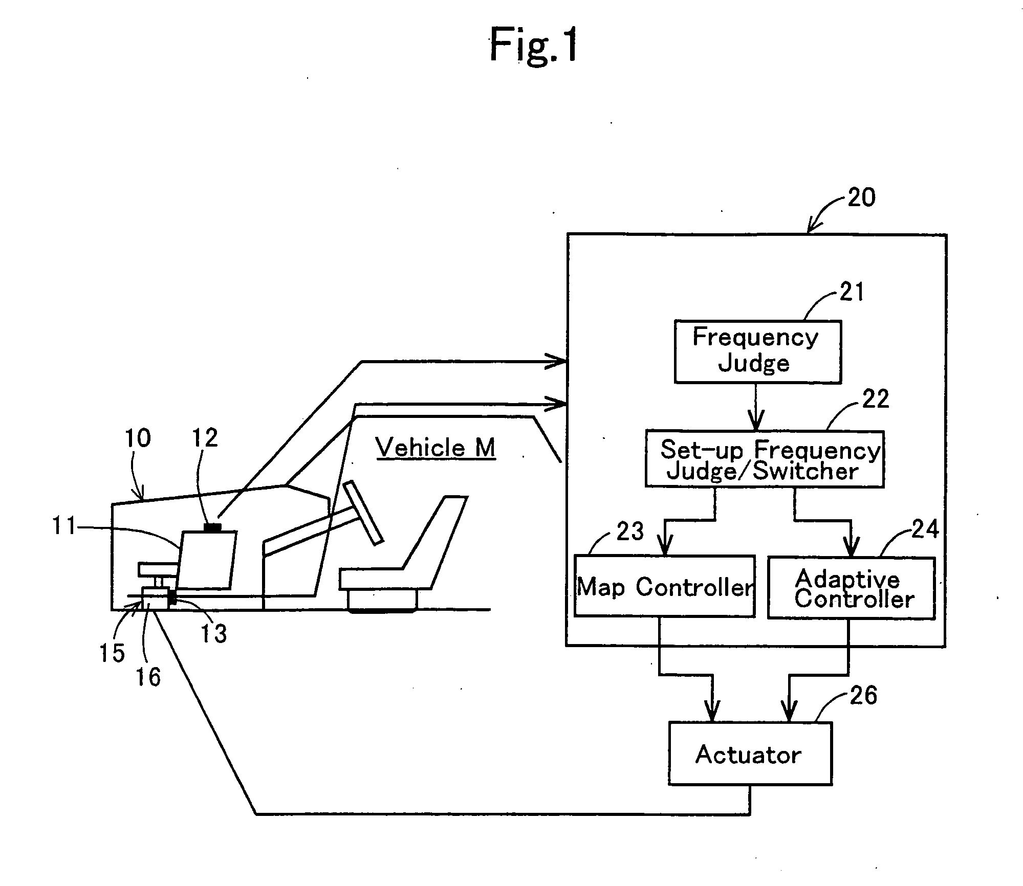
[0014] As described above, the vibration controller according to the first aspect of the present invention switches from the map controller to the adaptive controller or vice versa based on the frequency of the cyclically pulsating signal. Accordingly, the present vibration controller demonstrates the advantage of the map controller, the quick control response, as well the advantage resulting from the adaptive control method which can cope adequately with various driving conditions of vehicles. Consequently, the present vibration controller can inhibit vehicles from vibrating over a wide range from vehicles under idling to vehicles under running.
[0053] Moreover, when the vibration generating source is disposed on a sub frame of the vehicle, the present invention switches from the adaptive control method to the map control method if the frequency of the cyclically pulsating signal is a set-up frequency or more, set-up frequency which is lower than a resonance frequency. Accordingly, the present invention can quickly respond to resonant vibrations to damp them. Consequently, the present invention can securely inhibit the occurrence of out-of-control state resulting from the oscillation of the control signal.

Problems solved by technology

Accordingly, in a range of vibration whose frequency is as low as 50 Hz approximately, such as automobiles under idling, there arises a problem that the vibration control might impair the ride quality, because passengers might perceive the vibration intensely.
When such a resonant vibration is added to the inherent vibration of vehicle, the phase of control signal might possibly become unstable because the control response has been retarded in an adaptive control method.
In this instance, there might arise a fear that the control signal oscillates to result in loss of control.
On the other hand, in the map control method, the number of data maps are limited.
Accordingly, there arises a problem that it is difficult to cope with controls which require a large number of data maps depending on control conditions.
Consequently, it is difficult for the map control method to fully cope with various vibrations.
Thus, there is a problem that the map control method might impair the ride quality.

Method used


Image

  • Vibration controller for active vibration insulators and method for controlling vibrations for the same
  • Vibration controller for active vibration insulators and method for controlling vibrations for the same
  • Vibration controller for active vibration insulators and method for controlling vibrations for the same

Examples


example no.1

EXAMPLE NO. 1

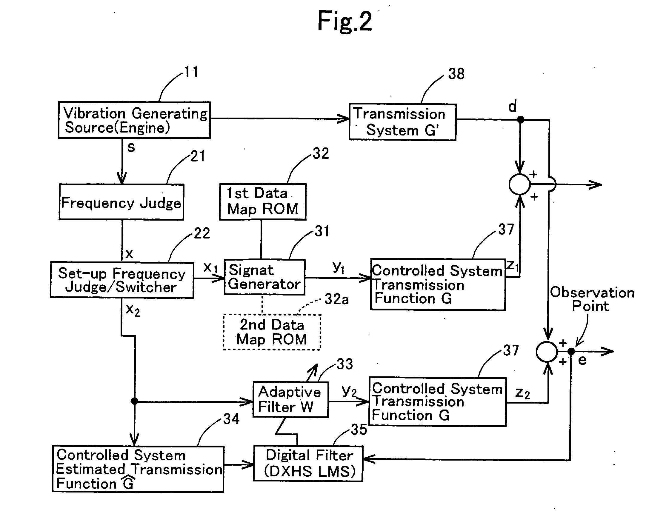
[0061]FIG. 1 roughly illustrates an arrangement of a vibration controller according to Example No. 1 of the present invention for a 6-cylidner and 4-cycle gasoline-engine-driven vehicle M by means of a schematic diagram. FIG. 2 roughly illustrates a control mode for removing vibrations by the vibration controller by means of a block diagram. FIG. 3 illustrates “Vibration Control Program No.1” executed by the vibration controller by means of a flowchart.

[0062] As illustrated in FIG. 1, the vehicle M comprises a vehicle body 10 which is equipped with an engine mount 15 provided with an actuator, an active vibration insulator, (hereinafter simply referred to as an “engine mount”). The engine mount 15 supports an engine 11, a vibration generating source. The engine mount 15 comprises a cylinder-shaped housing (not shown), a vibration insulator rubber (not shown) disposed in the cylinder-shaped housing, and an electromagnetic actuator 16 disposed in the cylinder-shaped hous...

example no.2

EXAMPLE NO. 2

[0077] A vibration controller according to Example No. 2 of the present invention will be hereinafter described.

[0078] The vibration controller according to Example No. 2 of the present invention copes with the case where the engine 11 is installed to a sub frame (not shown) of the vehicle M. Specifically, the vibration controller copes with the case where a vibration of the sub frame resonates to a vibration of the engine 11 in a high-frequency range of higher than 50 Hz, especially in a high-frequency range of 80 Hz or more, in the range of vehicle under running. In the vibration controller, a data map on control signals for a high-frequency range of 80 Hz or more, which is higher than the set-up frequency Fs and which is a second set-up frequency Fsr or more, for example, 80 Hz or more, the second set-up frequency Fsr being lower than a resonance frequency resonating to the vibration of the sub frame, is found in advance using the adaptive controller 24. Moreover, t...


PUM


Abstract

A vibration controller includes a map controller, an adaptive controller, a set-up frequency judge / switcher, and an actuator. The map controller includes a data map storage for storing data on control signals determined in advance for a vibration insulator, and a signal generator for selecting one of the data, depending on a frequency of a cyclically pulsating signal emitted from a vibration generating source of a vehicle, from the data map storage and generating a control signal. The adaptive controller generates the control signal with respect to the cyclically pulsating signal using an adaptive control method. The set-up frequency judge / switcher switches from the map controller to the adaptive controller or vice versa based on the frequency of the cyclically pulsating signal. The actuator actuates an actuator of the vibration insulator based on the control signal generated by the map controller or the adaptive controller, whereby inhibiting the vehicle from vibrating.

Description

BACKGROUND OF THE INVENTION [0001] 1. Field of the Invention [0002] The present invention relates to a vibration controller and a vibration control method for active vibration insulators, vibration controller and method which can actively inhibit vehicles from vibrating. [0003] 2. Description of the Related Art [0004] As disclosed in Japanese Unexamined Patent Publication (KOKAI) No. 8-44, 377 and Japanese Unexamined Patent Publication (KOKAI) No. 2001-140, 974, an adaptive control method, for example, an adaptive control method which uses an adaptive minimum mean squared filter, (hereinafter referred to as “Filtered-X LMS” filter) or a retarded harmonic synthesizer minimum mean squared filter (hereinafter referred to as “DXHS LMS” filter), has been applied to controlling the vibrations of an engine mount equipped with an actuator, an automotive active vibration insulator. In an adaptive control method, the filter coefficient of a “Filtered-X LMS” filter is updated sequentially to c...

Claims


Application Information

Patent Timeline
IPC IPC(8): B60K5/12F16F15/00F16F15/02G05B13/02G05D19/02G06F7/00
CPCF16F15/002G05D19/02G05B13/0245
Inventor ICHIKAWA, HIROYUKIMURAMATSU, ATSUSHIYASUDA, TAKAYOSHI
Owner TOKAI RUBBER IND LTD
Learn More