Power supply circuitry and adaptive transient control

a power supply circuit and transient control technology, applied in the direction of process and machine control, image enhancement, instruments, etc., can solve the problems of reducing and producing output voltages with magnitudes, so as to improve the efficiency of power supply circuits and control the effect of speeding up the control response, reducing time, and increasing curren

Active Publication Date: 2012-08-23
INFINEON TECH AMERICAS CORP
View PDF10 Cites 9 Cited by
  • Summary
  • Abstract
  • Description
  • Claims
  • Application Information

AI Technical Summary

Benefits of technology

[0072]In other words, the control circuitry 140 can be configured such that a delay between receiving the error voltage in the second circuit path and generating corresponding period setting information 154-1 can be less than half or substantially smaller than the delay or amount of time between receiving the error voltage in the first circuit path and generating corresponding pulse width setting information 154-2. Again, the second circuit path lacks a duplication of the filter circuitry (e.g., one or more poles found in the first path) in order to provide a substantially faster control response than the first circuit path.
[0073]While in the pulse frequency modulation mode, the control circuitry 140 reduces an amount of time between high side switch activation pulses to increase an amount of current to a load; the control circuitry 140 increases an amount of time between high side switch activation pulses to decrease an amount of current to the load.

Problems solved by technology

Conventional applications such as those as discussed above can suffer from a number of deficiencies.
For example, conventional power supplies typically cannot provide a sufficiently fast response to large changes in current demand.
For example, if a conventional power supply outputs 50 amperes of current to power a load, and the load instantaneously changes and only requires 2 amperes, the conventional power supply may inadvertently produce an output voltage having a magnitude outside a tolerable range.
In such an instance, a device powered by the output voltage may be damaged.
Conversely, if a conventional power supply outputs 2 amperes of current to power a load, and the load instantaneously requires 50 amperes, the conventional power supply may not be able to produce sufficient output current to prevent the output voltage from falling below or outside a tolerable range due to excessive current consumption.

Method used


Image

  • Power supply circuitry and adaptive transient control
  • Power supply circuitry and adaptive transient control
  • Power supply circuitry and adaptive transient control

Examples


Embodiment Construction

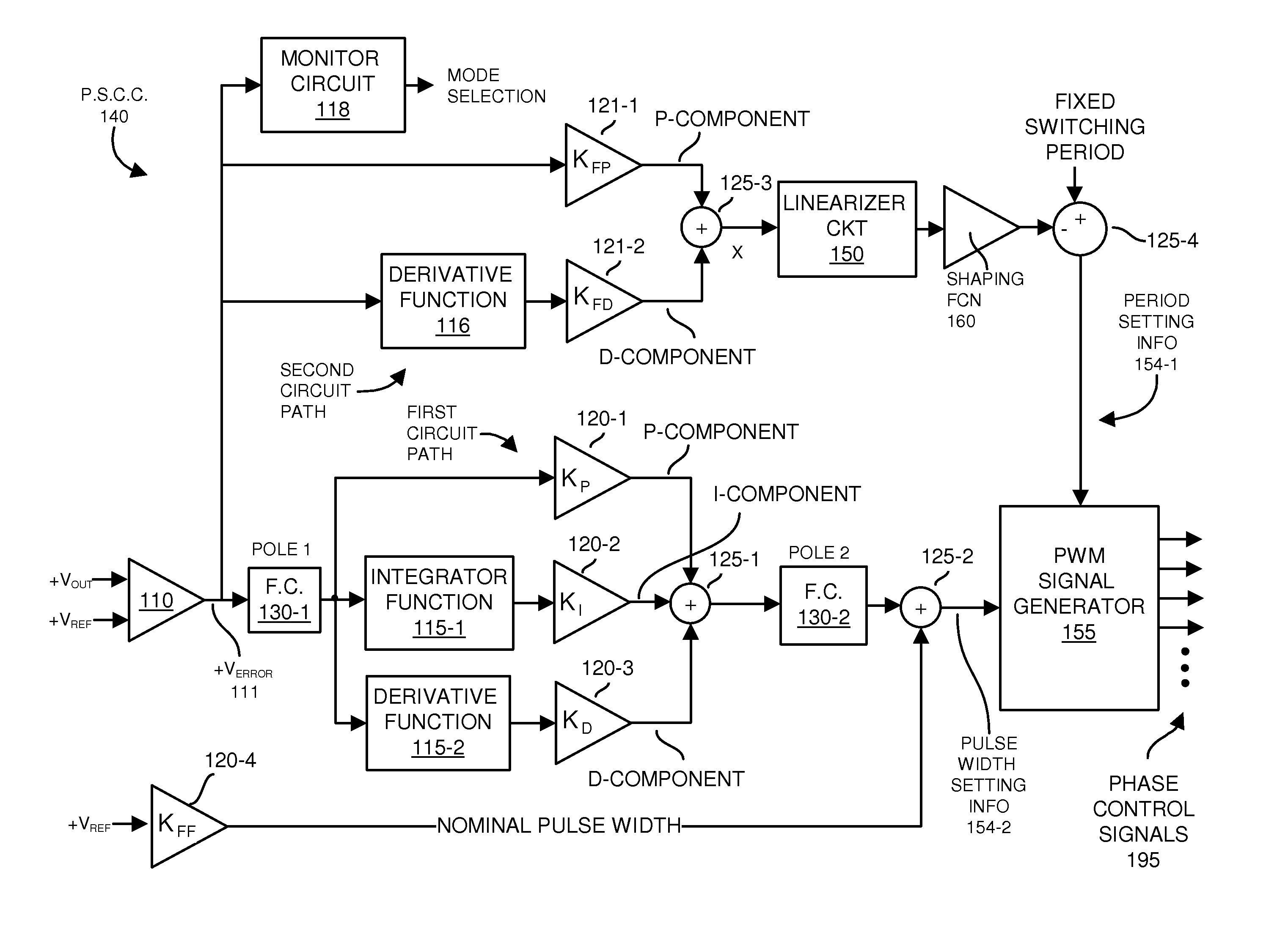
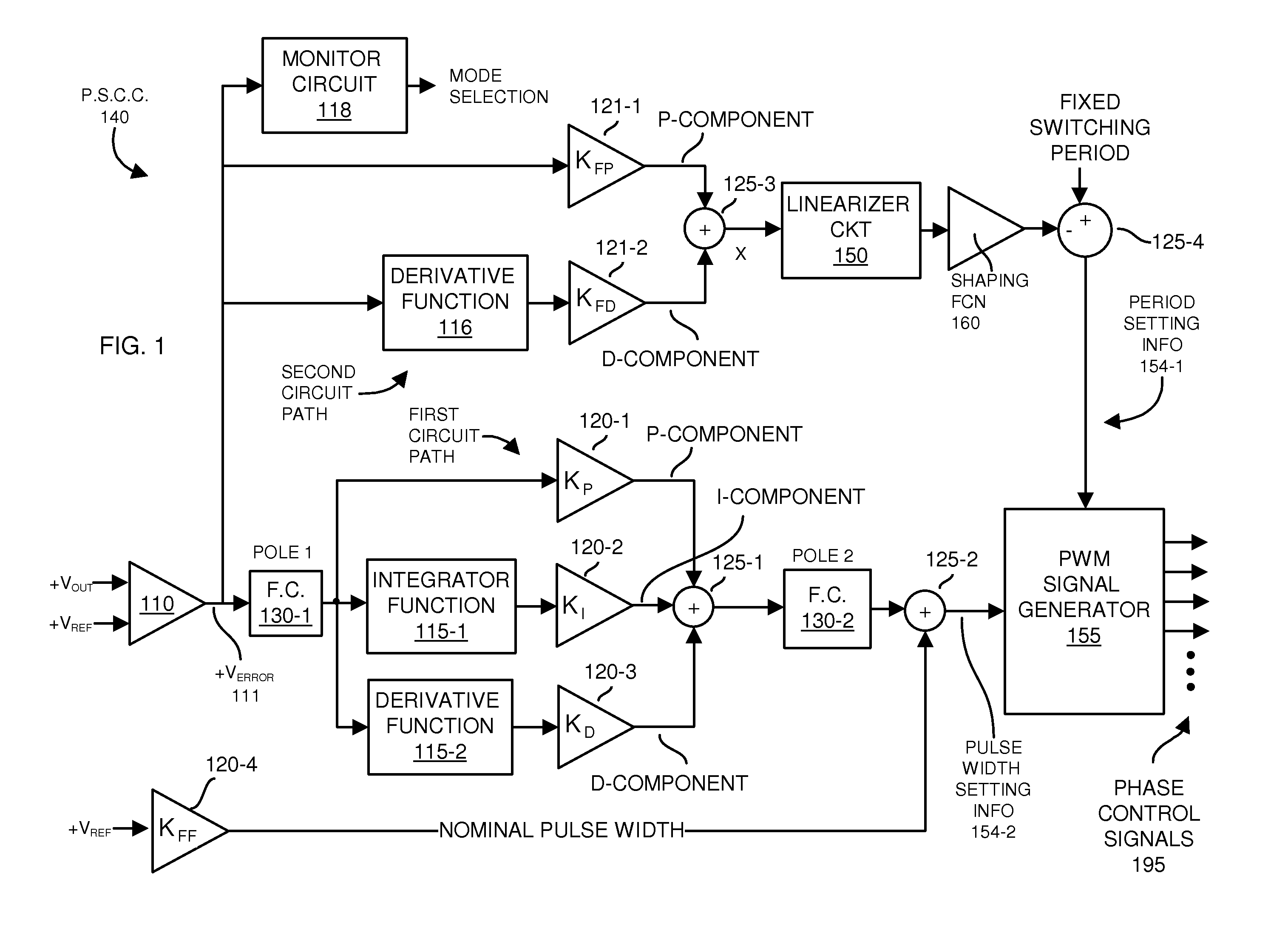
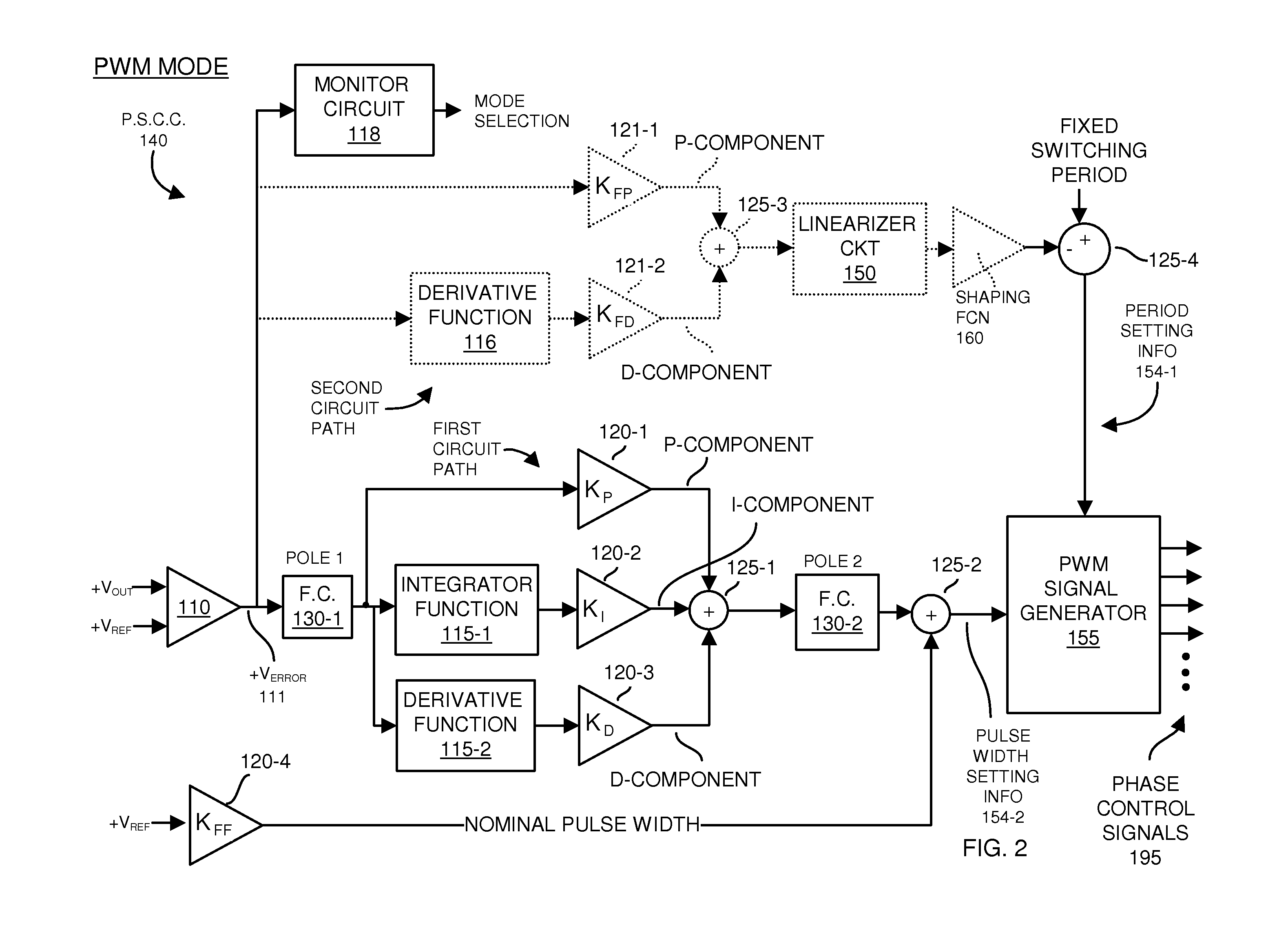
[0038]Embodiments herein include a multi-path control circuit configured to switch between operating in a pulse width modulation module and a pulse frequency modulation mode. A first circuit path of the multi-path control circuit supports the pulse width modulation mode; a second circuit path of the multi-path control circuit supports the pulse frequency modulation mode. When in the pulse width modulation mode, the control circuitry utilizes the first circuit path to adjust a pulse width setting for a pulsed control signal having a substantially fixed frequency. In the pulse frequency modulation mode, the control circuitry uses the second circuit path to adjust a period setting (e.g., frequency) for a pulsed control signal having a substantially fixed pulse width.

[0039]More specifically, FIG. 1 is an example diagram of power supply control circuitry according to embodiments herein. During operation, the power supply control circuitry 140 generates one or more phase control signals 1...


PUM


Abstract

A control circuitry can be configured to receive an error signal indicating a difference between an output voltage of the power supply and a desired setpoint for the output voltage. According to one configuration, depending on the error signal, the control circuitry initiates switching between operating the control circuitry in a pulse width modulation mode and operating the control circuitry in a pulse frequency modulation mode to produce an output voltage. Operation of the control circuitry in the pulse frequency modulation mode during a transient condition, such as when a dynamic load instantaneously requires a different amount of current, enables the power supply to satisfy current consumption by the dynamic load. Subsequent to the transient condition, the control circuitry switches back to operation in the pulse width modulation mode.

Description

RELATED APPLICATIONS[0001]This application is related to and claims the benefit of earlier filed U.S. Provisional Patent Application Ser. No. 61 / 445,587 entitled “ADAPTIVE CONTROL DURING A TRANSIENT,” (Attorney Docket No. CHL11-01p), filed on Feb. 23, 2011, the entire teachings of which are incorporated herein by this reference.BACKGROUND[0002]A conventional voltage regulator module (e.g., a VRM) can be used to regulate a DC voltage supplied to a load, such as a microprocessor. A VRM can include a power converter, such as a DC-DC converter, and may include other components such as a control circuitry for controlling operation of the power converter.[0003]An example of a DC-DC converter is a synchronous buck converter, which has minimal components, and therefore is widely used in VRM applications. In an example conventional application, the input voltage to the buck converter is typically 12VDC. An output voltage produced by the VRM may be 5.0VDC, 3.3 VDC, or lower.[0004]Conventional...

Claims


Application Information

Patent Timeline
Patent Type & Authority Applications(United States)
IPC IPC(8): G05F1/10
CPCG06K9/6226G06T7/0081G06T7/0087G06T2207/30081G06T2207/20081G06T2207/20144G06T2207/20156G06T2207/10088H02M3/1588H02M3/1566Y02B70/10
Inventor SREENIVAS, VENKATCARROLL, ROBERT T.
Owner INFINEON TECH AMERICAS CORP
Why Eureka
Try Eureka