
Structure for suspending filter plate and suspending style thereof

A filter plate and hanger technology, applied in separation methods, filtration separation, chemical instruments and methods, etc., can solve the problems of being easily corroded by materials, unable to solve filter plate shaking, etc., and achieve the effect of novel structure

Active Publication Date: 2009-07-29
杭州兴源环保设备有限公司
View PDF2 Cites 0 Cited by
  • Summary
  • Abstract
  • Description
  • Claims
  • Application Information

AI Technical Summary

Problems solved by technology

Its shortcomings are: the metal girders on both sides are close to the side of the filter plate, which is easily corroded by the material; it cannot solve the shaking of the filter plate during the moving process, which directly affects the stability and reliability of the filter plate machine.

Method used


Image

  • Structure for suspending filter plate and suspending style thereof
  • Structure for suspending filter plate and suspending style thereof
  • Structure for suspending filter plate and suspending style thereof

Examples


Embodiment 1

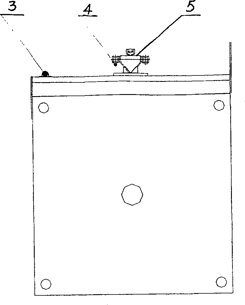
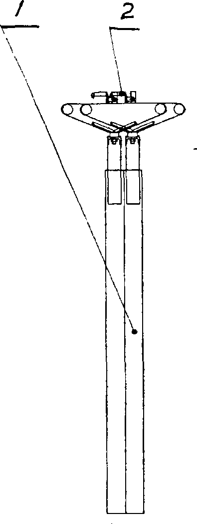
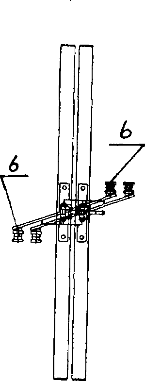
[0012] Embodiment 1: with reference to attached Figure 1~3 . The suspension structure of the filter plate, the rollers 6 located on both sides of the hanger 5 with an inverted triangle cross section are not on the same axis, refer to the attached figure 1 and 3 . The claw tongue 2 is located at the upper end of the inverted triangular hanger 5 and between the rollers 6. The steel frame at the upper end of the filter plate 1 is provided with an inverted V-shaped seat 7 in section and connected with the corner of the lower part of the inverted triangular hanger 5. Refer to the attached figure 1 and 2 . One side of the upper end of the filter plate 1 is provided with a guide rod ring and cooperates with the guide rod 3 .

[0013] Refer to attached Figure 4 . The pull plate mechanism of the filter press, the claw tongue 2 is a lever structure and is processed and manufactured by the existing technology. The claw tongue 2 is located on the top of the filter plate, and th...

Embodiment 2

[0014] Embodiment 2: on the basis of embodiment 1, with reference to appended Figure 4 . The filter plate suspension method includes the filter plate suspension system. The rollers located on both sides of the hanger with an inverted triangle cross section are located on the left and right guide rails inside the suspension beam. The two rollers form a certain angle with the filter plate surface. One side of the top corner is pierced, and the claw tongue can hang the adjacent filter plate. There are many puller hooks on the puller chain in the suspension beam, which are driven by a motor to run counterclockwise. These pull plate hooks slide on the suspension mechanism of the filter plate. When sliding to the last filter plate, they cross the claw tongue on the suspension mechanism. The pull plate hooks fall by their own weight and mesh with the claw tongue on the suspension mechanism. At this time, the claw The tongue is pressed down, the claw hook is lifted, the self-lockin...


PUM


Abstract

The invention relates to a filter plate suspension structure and suspension method, which includes a filter plate suspension system, rollers located on both sides of a hanger with an inverted triangular cross section located on the left and right guide rails inside the suspension beam, and the two rollers form a certain angle with the surface of the filter plate , the guide rod pierces the top corner of one side of each filter plate, and the claw tongue can hang the adjacent filter plate. Advantages: First, it solves the problem that the side beams of the side beam installation method in the background technology are easily corroded by materials; second, the filter plate shakes back and forth during the movement of the filter plate of the side beam installation method; Simple and reliable.

Description

Technical field: [0001] The invention relates to a suspension installation structure and a suspension mode of a filter plate, and belongs to the field of filter press component assembly manufacturing. Background technique: [0002] In the existing filter plate installation structure, in terms of structural design, what is used to support the filter plate is the support lug guide rail structure located on both sides of the filter plate, and the support lugs are provided with rollers and located on the guide rails. When working, the filter plate is driven by the external drive mechanism, and the rollers in the supporting ears on both sides of the filter plate move along the guide rail. Its shortcomings are: the metal girders on both sides are close to the side of the filter plate, which is easily corroded by the material; it cannot solve the shaking of the filter plate during the moving process, which directly affects the stability and reliability of the filter plate machine. ...

Claims


Application Information

Patent Timeline
Patent Type & Authority Patents(China)
IPC IPC(8): B01D25/12B01D25/172
Inventor 张景倪国炳孙自忠陈科庆
Owner 杭州兴源环保设备有限公司
Learn More