Horizontal broacher

A horizontal, bed-body technology, used in broaching, broaching devices, metal processing, etc., can solve the problems of long broach return time and reduced broaching efficiency.

Active Publication Date: 2009-07-29
CHAGYI LIHUI BROACHING MACHINE MAFACTURE
View PDF7 Cites 3 Cited by
  • Summary
  • Abstract
  • Description
  • Claims
  • Application Information

AI Technical Summary

Problems solved by technology

[0004] The technical problem to be solved by the present invention is to provide a horizontal broaching machine to solve the problem of long return time of the broach and lower working efficiency of the broaching machine

Method used


Image

  • Horizontal broacher
  • Horizontal broacher
  • Horizontal broacher

Examples


Embodiment Construction

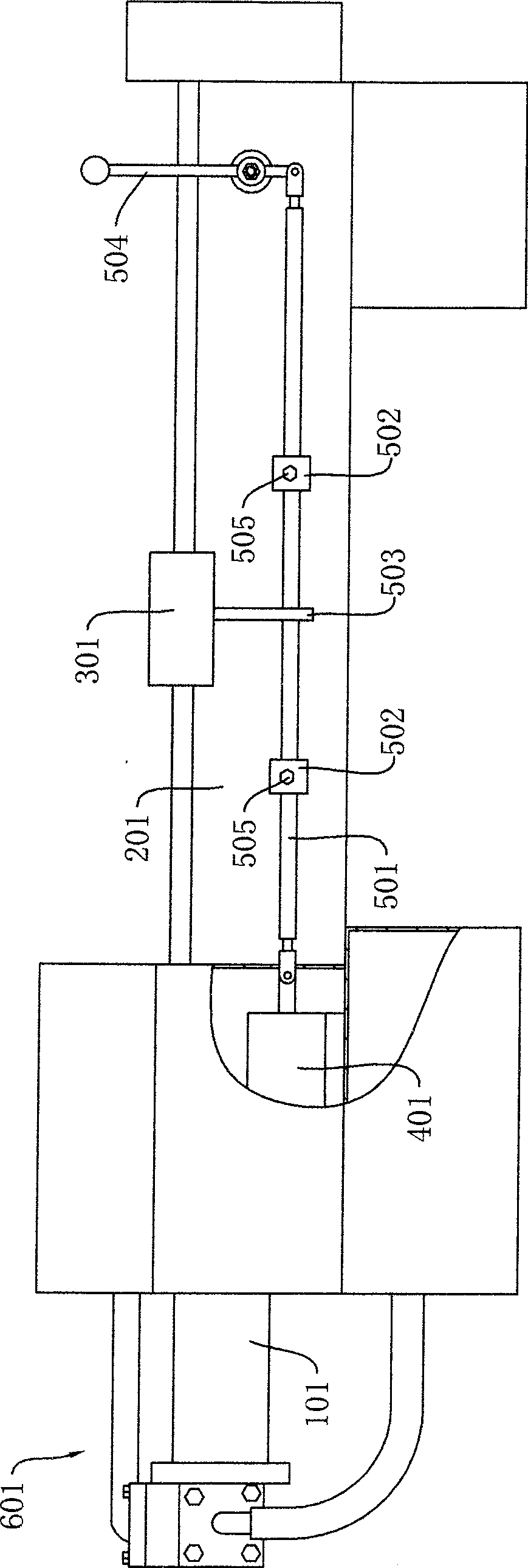
[0020] A horizontal broaching machine, such as figure 1 As shown, the hydraulic cylinder 101 and the manual reversing valve 401 are installed on the bed body 201, the piston rod of the hydraulic cylinder 101 and the broach are fixedly connected together through the chuck, and the chuck and the sliding seat that can slide along the guide rail of the bed body 201 301 fixed connection. The differential valve 601 is fixedly connected to the rodless cavity end of the cylinder body of the hydraulic cylinder 101 .

[0021] An operating device is provided between the sliding seat 301 and the valve stem of the manual reversing valve 401, and the specific structure is as follows: the joystick 501 is connected with the valve stem of the manual reversing valve 401, and is hinged with the operating handle 504 at its other end , the operating handle 504 is hinged with the bed body 201 at an appropriate position. The joystick 501 and the manual reversing valve 401 are preferably hinged, wh...


PUM


Abstract

The invention discloses a horizontal broaching machine. The invention mainly has the following technical points: a speed-difference valve is arranged between a hydraulic cylinder and a reversing valve; the moving speed of a piston of the hydraulic cylinder can be raised by more than two times when a high-pressure oil is fed into a non-rod cavity of the hydraulic cylinder and then the return time of a broach can be largely shortened and the work efficiency of the broaching machine can be enhanced. One the other hand, a manual reversing valve is adopted, and a mechanical operation device is arranged between the manual reversing valve and a sliding seat. The operation device can drive a valve rod of the manual reversing valve to move when the sliding seat moves to a corresponding position so as to realize an automatic reversing of the hydraulic cylinder. Compared with a reversing device formed by a solenoid directional valve and a stroke switch, the invention has the advantages that the use is reliable; the regulation is convenient; the structure is simple and the manufacturing cost is low.

Description

technical field [0001] The invention relates to the technical field of broaching machines, in particular to a horizontal broaching machine. Background technique [0002] For a horizontal broaching machine, the broach is fixed together with the piston rod of the hydraulic cylinder through a collet. Under the control of the hydraulic system, the broaching operation is realized when the piston rod retracts, and the broaching operation is realized when the piston rod is extended. return. Since the broach and the piston rod are pulled when retracting, the rigidity is good and it is not easy to deform, so the accuracy of the workpiece can be guaranteed. When the broach is stretched out, it is an empty stroke and is not subject to broaching force, thus avoiding the broach and piston rod. It is easy to lose stability in the compressed state, resulting in deflection and deformation, which affects the processing accuracy. From the perspective of improving work efficiency, the return...

Claims


Application Information

Patent Timeline
Patent Type & Authority Patents(China)
IPC IPC(8): B23D41/08B23D37/02F15B15/22B23Q5/54
Inventor 田立辉
Owner CHAGYI LIHUI BROACHING MACHINE MAFACTURE
Why Eureka
Try Eureka