Electromagnetic actuating device

A control device and electromagnetic technology, applied in the direction of electromagnet, valve device, valve operation/release device, etc., can solve the problems of complex manufacturing and magnetic force reduction, and achieve the effects of simplified manufacturing, simple cost, and avoiding the weakening of the magnetic circuit

Pending Publication Date: 2020-06-30
ROBERT BOSCH GMBH
View PDF1 Cites 0 Cited by
  • Summary
  • Abstract
  • Description
  • Claims
  • Application Information

AI Technical Summary

Problems solved by technology

In addition to the manufacturing complexity, this can also lead to throttling of the magnet

Method used


Image

  • Electromagnetic actuating device
  • Electromagnetic actuating device
  • Electromagnetic actuating device

Examples


Embodiment Construction

[0026] Electromagnetic control device in Figure 1aThe center bears the reference numeral 10 as a whole. Such electromagnetic actuating devices 10 are used, for example, in the transmission technology of motor vehicles, in particular for controlling clutches of automatic transmissions. For this purpose, hydraulic valves are actuated, for example, by electromagnetic actuation device 10 , said hydraulic valves Figure 1a is only schematically delineated by the box provided with the reference number 12 ).

[0027] The electromagnetic actuating device 10 has a housing 14 in which the components of the electromagnetic actuating device 10 are arranged. The electromagnetic actuating device 10 has a solenoid coil 16 which has a coil body 18 and a winding 20 . At the first end side 22 the housing 14 is closed by means of a closure 24 which can be a flux disk. On the second end side 26 the housing is closed by means of a cover 28 which can be a magnet cover 28 . Furthermore, an elect...


PUM


Abstract

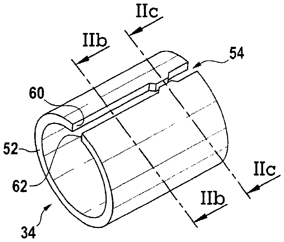
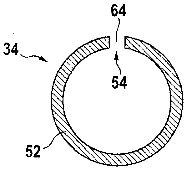
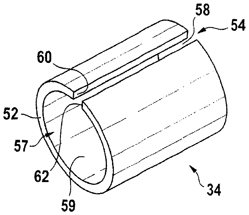
The invention relates to an electromagnetic actuating device (10) comprising a sleeve (34), an armature (32) arranged radially inside the sleeve (34), and an electromagnetic coil (16) arranged radially outside the sleeve (34), wherein the armature (32) has a first armature end face (48) at one end and a second armature end face (50) at the opposite end. It is proposed that the sleeve (34) has, onor in a sleeve wall (52), a channel (54) extending in the longitudinal direction (46) of the sleeve (34), by means of which a flow connection is formed between the armature end sides (48, 50).

Description

technical field [0001] The invention relates to an electromagnetic actuation device according to the preamble of claim 1 . Background technique [0002] In automatic passenger car transmissions, hydraulically actuated clutches are used for shifting gears, the hydraulic pressure on the clutches being adjusted via hydraulic slide valves. The slide valve can be actuated via a pilot valve (pilot ventil; pilot control) or directly via a solenoid actuation. In order to achieve damping, such actuating devices are filled with oil, wherein when the armature of the actuating device moves, the oil is squeezed out of the reduced space before the armature and is pumped through the overflow channel to the transformer after the armature. in a large space. Damping of the armature movement is produced by this pumping process. Since the transmission oil has a high air absorption capacity, the problem arises in practice of fluctuations in the oil level in the armature chamber, which makes c...

Claims


Application Information

Patent Timeline
IPC IPC(8): F16K31/06H01F7/16H01F7/08
CPCF16K31/0675F16K31/0696H01F7/1607H01F7/081H01F2007/085H01H50/18
Inventor K.舒特M-F.森
Owner ROBERT BOSCH GMBH
Why Eureka
Try Eureka