
Frame-supporting column with high strength steel bars and super high strength concrete

A technology of ultra-high-strength concrete and high-strength steel bars, which is applied in the direction of pillars, columns, pier columns, etc., can solve the problems of concrete protective layer falling off, less transverse restraint stirrups, etc., and achieves convenient node handling, reduced cross-sectional size, and good fluidity Effect

Inactive Publication Date: 2013-04-17
贵州中建伟业建设(集团)有限责任公司
View PDF5 Cites 9 Cited by
  • Summary
  • Abstract
  • Description
  • Claims
  • Application Information

AI Technical Summary

Problems solved by technology

The invention solves the problem that the concrete protective layer of the existing ordinary reinforced concrete frame pillars, high-strength reinforced concrete frame pillars, and steel concrete frame pillars falls off under the action of earthquake force, so that the steel bars with a yield strength greater than 800 MPa can be applied to concrete columns Compared with concrete-filled steel tube frame pillars, the present invention has the advantages of good restraint effect, less transverse restraint stirrups, and strong economy

Method used

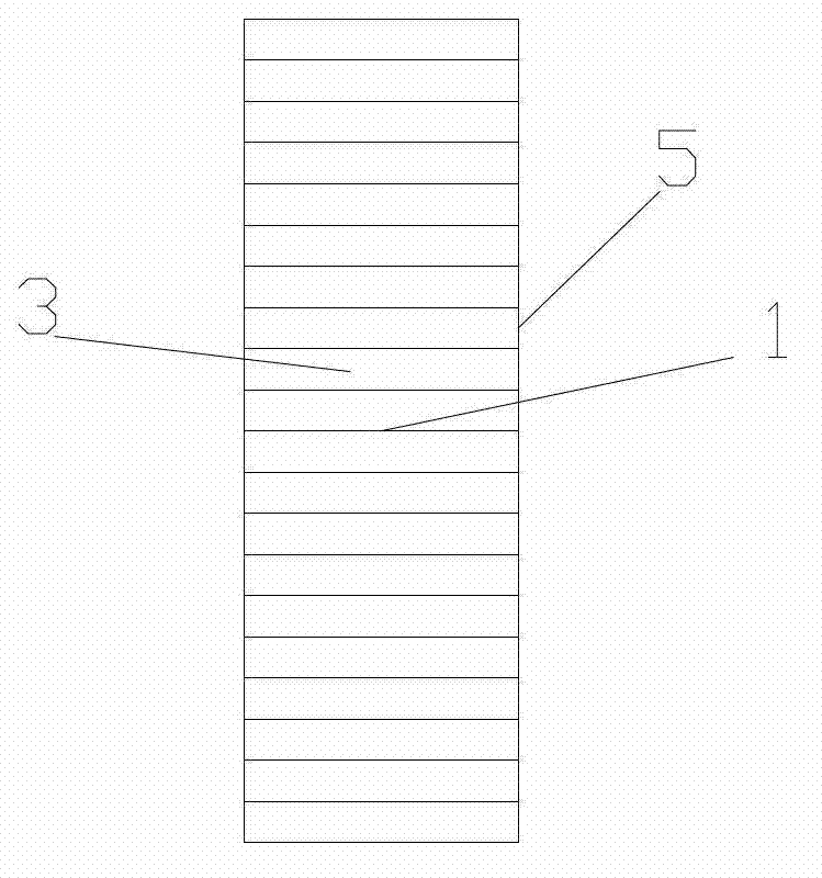
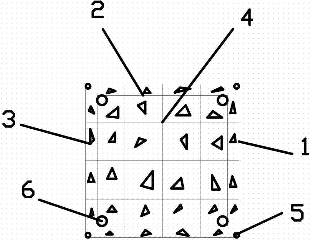

Image

  • Frame-supporting column with high strength steel bars and super high strength concrete
  • Frame-supporting column with high strength steel bars and super high strength concrete
  • Frame-supporting column with high strength steel bars and super high strength concrete

Examples


Embodiment Construction

[0036] All longitudinal steel bars and stirrups are processed by professional steel bar processing companies through CNC steel bar processing machines. The size error of longitudinal steel bars is controlled within ±5mm, and the size error of stirrups is controlled within ±1mm.

[0037] The closed stirrup 7 can be obtained by lap welding, double-sided welding, the lap length is not less than 5d, and single-sided welding, the lap length is not less than 10d, where d is the diameter of the steel bar.

[0038] Tie bar 4 should leave a 90-degree hook on both sides during processing. The length of the horizontal section of the hook is not less than 5d when double-sided welding, and the length is not less than 10d when single-sided welding, where d is the diameter of the steel bar.

[0039] Closed stirrups 1 and 2 are obtained by welding closed stirrups 7 and tie bars 4 .

[0040] Bind the stirrups and longitudinal steel bars according to the design drawings, support the formwork, a...


PUM


Abstract

The invention relates to a reinforced concrete frame-supporting column, in particular to a frame-supporting column with high strength steel bars and super high strength concrete. The frame-supporting column overcomes defects that axial compression ratio limits of ordinary reinforced concrete frame-supporting columns and steel reinforced concrete frame-supporting columns are low, protective covers fall easily under earthquake force, longitudinal bars and steel flanges are easy to bend, the columns are difficult to repair after an earthquake, and high strength steel bars and super high strength concrete cannot be applied, and defects that node constructions of steel reinforced concrete and steel pipe concrete frame-supporting columns are complex, the steel pipe concrete frame-supporting columns do not constrain concrete fully, and steel pipes are easy to bend. The frame-supporting column comprises longitudinal high strength steel bars, high strength closed stirrups and self-compaction super high strength concrete; and constraints include that stirrup spacing of concrete protective covers in whole concrete ranges from 30mm to 35mm, outer surfaces are aligned to outer surfaces of concrete frame-supporting columns, and the stirrup spacing of longitudinal high strength steel bars is constrained to range from 60 mm to 120 mm. By aid of constraining of closely-matched high strength welding closed stirrups on the whole concrete, mechanical properties of super high strength concrete are improved, anti-seismic properties of the column are improved, and the frame-supporting column has a wide application prospect in high-rise or super high-rise structures.

Description

technical field [0001] The invention belongs to a building structure component and relates to a reinforced concrete frame pillar. Background technique [0002] Due to the functional requirements of the building, there is a large space in the lower part, and the vertical components in the upper part cannot be directly connected to the ground, but are connected to the vertical components in the lower part through a horizontal conversion structure. When a transfer beam is arranged to support an upper column or shear wall, the columns supporting the transfer beam are called frame columns. [0003] At present, there are several types of frame pillars: 1. Ordinary reinforced concrete frame pillars; 2. High-strength reinforced concrete frame pillars; 3. Steel concrete frame pillars; 4. Steel tube concrete frame pillars. [0004] At present, the yield strength of the section steel and steel pipe used in the frame pillar, the longitudinally stressed steel bar and the stirrup are all...

Claims


Application Information

Patent Timeline
Patent Type & Authority Applications(China)
IPC IPC(8): E04C3/34E04B1/98
Inventor 管俊峰姚贤华王慧张谦张晓燕赵顺波李长永
Owner 贵州中建伟业建设(集团)有限责任公司
Learn More