
Semi-precast concrete filled steel tubular column with built-in high-strength structural steel and manufacturing method thereof

A technology for concrete filled steel tubular columns and precast concrete, applied in the field of concrete columns, can solve the problems of difficulty in transportation and hoisting, weakening of the integrity of the column, and reduced mechanical performance, and achieves the effects of reducing self-weight, cost, and section size.

Active Publication Date: 2016-09-07
SOUTH CHINA UNIV OF TECH
View PDF5 Cites 12 Cited by
  • Summary
  • Abstract
  • Description
  • Claims
  • Application Information

AI Technical Summary

Problems solved by technology

However, if the column is prefabricated as a whole, due to its heavy weight, it will bring great difficulties to subsequent transportation and hoisting; if the column is prefabricated in sections and then spliced ​​on site, it may be weakened due to the integrity of the column. Reduced force performance

Method used


Image

  • Semi-precast concrete filled steel tubular column with built-in high-strength structural steel and manufacturing method thereof
  • Semi-precast concrete filled steel tubular column with built-in high-strength structural steel and manufacturing method thereof

Examples


Embodiment 1

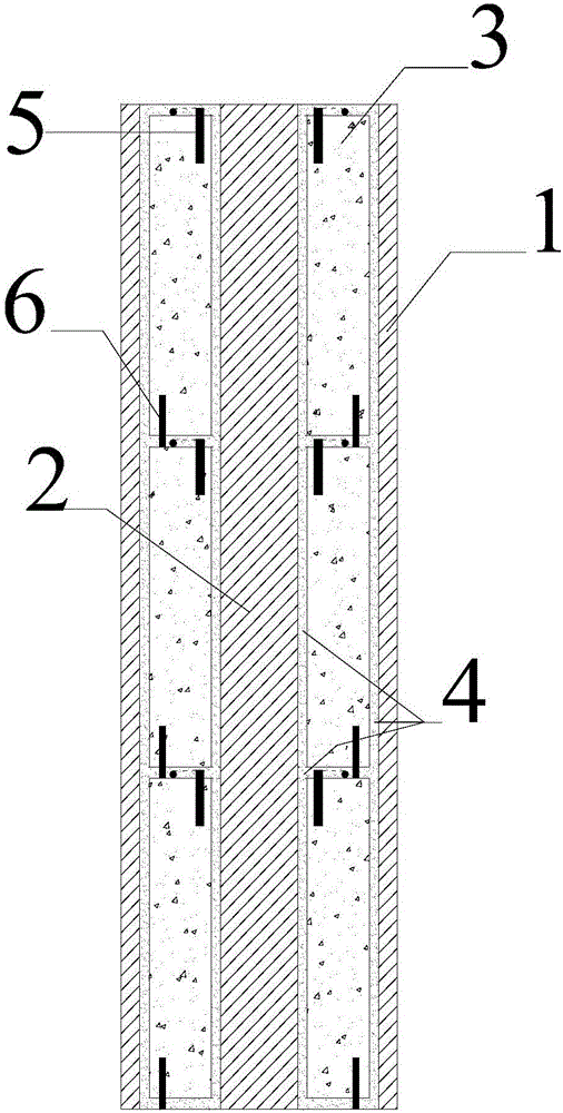
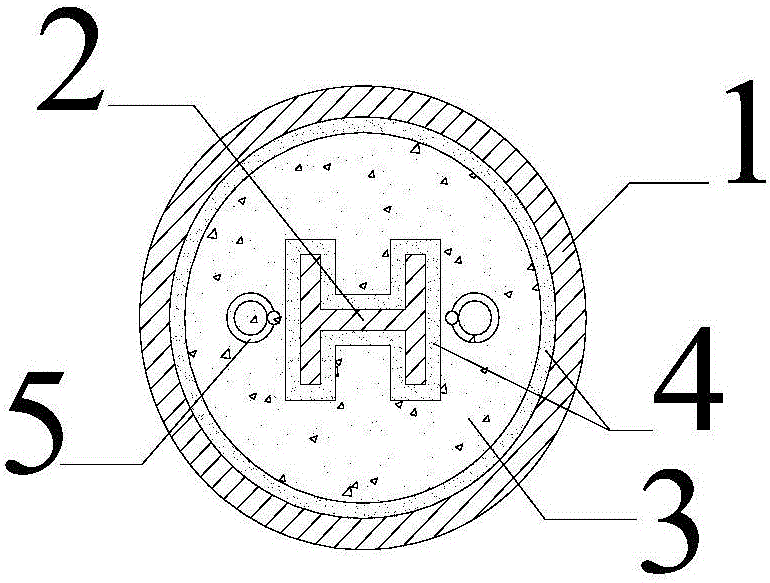
[0028] Such as figure 1 , 2 shown. The invention discloses a semi-prefabricated steel pipe concrete column with built-in high-strength section steel, which comprises a steel pipe 1, a plurality of mutually spaced prefabricated concrete segments 3 arranged vertically inside the steel pipe 1; the inner wall of the steel pipe 1 and the prefabricated concrete Leave a gap between the outer walls of section 3;

[0029] Each prefabricated concrete segment 3 is pre-embedded with a suspension ring device 5 protruding from its top and a short steel bar 6 protruding from its bottom;

[0030] The middle part of each prefabricated concrete segment 3 is reserved with an axially penetrating shaped steel channel, which is used to place the shaped steel 2; there is a gap between the wall surface of the shaped steel channel and the outer surface of the shaped steel 2;

[0031] The inside of the steel pipe 1 is filled with grouting material 4; the grouting material 4 fills the gaps between th...

Embodiment 2

[0045] This embodiment is the same as Embodiment 1 except for the following features.

[0046] The cross-section of the steel pipe 1 is circular, with an outer diameter of 1500mm and a wall thickness of 30mm. The length of the steel pipe 1 is 3660mm, the steel grade is Q345, and the measured yield strength is 400MPa; each precast concrete segment 3 is a cylinder with a diameter of 1420mm and a height of 1200mm, the gap between the wall surface of the upper and lower penetrating section steel channel reserved in the middle and the outer surface of the section steel 2 is 5mm, and the concrete compressive strength is 50MPa; The height is 9mm; the cross-sectional area of ​​the welded H-shaped steel is 1480.55cm2, the steel grade is Q890, and the measured yield strength is 900MPa; the grouting material is epoxy resin chemical grouting material.

[0047] For comparison, a circular steel pipe of the same material with an outer diameter of 1500 mm and a wall thickness of 30 mm is used...


PUM

PropertyMeasurementUnit
compressive strengthaaaaaaaaaa
yield strengthaaaaaaaaaa
diameteraaaaaaaaaa

Abstract

The invention discloses a semi-precast concrete filled steel tubular column with built-in high-strength structural steel and a manufacturing method thereof. The semi-precast concrete filled steel tubular column comprises a steel pipe and a plurality of precast concrete segments sequentially arranged in the steel pipe at intervals in the vertical direction; gaps are reserved between the inner wall of the steel pipe and the outer walls of the precast concrete segments; a vertical through structural steel channel is reserved in the middle of each precast concrete segment and used for mounting the structural steel; gaps are reserved between the walls of the structural steel channels and the outer surface of the structural steel; grouting materials are poured in the steel pipe; and the gaps between the precast concrete segments, the gaps between the walls of the structural steel channels and the outer surface of the structural steel and the gaps between the outer walls of the precast concrete segments and the inner wall of the steel pipe are all fully filled with the grouting materials. According to the manufactured semi-precast concrete filled steel tubular column with the built-in high-strength structural steel, under the requirement for the same bearing capacity, the sectional dimension of the column can be remarkably reduced, and therefore the usable area of a building is enlarged, and good economic and social benefits are achieved.

Description

technical field [0001] The invention relates to a concrete column, in particular to a semi-prefabricated steel tube concrete column with built-in high-strength section steel and a preparation method thereof. Background technique [0002] Due to the huge vertical loads of the lower columns of super high-rise building structures, their cross-sectional dimensions are usually large, which not only occupies more building space and affects the use of buildings, but also increases the seismic action of the structure due to the increase in the self-weight of the components. , which is detrimental to the seismic resistance of the structure. [0003] In recent years, the production and application of high-strength steel have become increasingly mature, and the use of this type of material is undoubtedly beneficial to reducing the cross-sectional size of the column. However, since the compression buckling of high-strength steel is often earlier than its compression yield, the advantag...

Claims


Application Information

Patent Timeline
Patent Type & Authority Applications(China)
IPC IPC(8): E04C3/32E04C3/34E04G21/14
CPCE04C3/32E04C3/34E04G21/14
Inventor 吴波申超
Owner SOUTH CHINA UNIV OF TECH
Learn More