Externally-wrapped steel plate reinforced concrete assembled shear wall and construction method thereof

A technology of reinforced concrete and combined shear walls, which is applied to walls, buildings, building components, etc. It can solve the problems that it is difficult to take into account the welding workload and the tension of steel plate walls, and achieve high construction efficiency, cost savings, and improved brittle failure Effect

Pending Publication Date: 2017-07-18
ARCHITECTURAL DESIGN RES INST OF GUANGDONG PROVINCE
View PDF8 Cites 0 Cited by
  • Summary
  • Abstract
  • Description
  • Claims
  • Application Information

AI Technical Summary

Problems solved by technology

[0004] The technical problem to be solved by the present invention is: to provide a steel plate reinforced concrete composite shear wall to overcome the problem in the prior art that it is difficult to take into account the welding workload and realize the tension between the two steel plate walls

Method used


Image

  • Externally-wrapped steel plate reinforced concrete assembled shear wall and construction method thereof
  • Externally-wrapped steel plate reinforced concrete assembled shear wall and construction method thereof
  • Externally-wrapped steel plate reinforced concrete assembled shear wall and construction method thereof

Examples


Embodiment 1

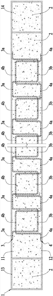
[0049] Such as figure 1 As shown, the first embodiment of the present invention is based on the above-mentioned inventive concept, and adopts the following specific schemes for the first stirrup 3 and the second stirrup 4:

[0050] In the first embodiment, the first stirrup 3 and the second stirrup 4 are formed by bending a steel bar; and the welding section 3a of the first stirrup 3 and the welding section 4a of the second stirrup 4 are both Linear type, the raised section 3b of the first stirrup 3 and the raised section 4b of the second stirrup 4 are both U-shaped.

Embodiment 2

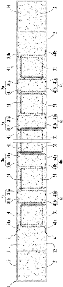
[0052] Such as figure 2 As shown, the second embodiment of the present invention is based on the above-mentioned inventive concept, and adopts the following specific schemes for the first stirrup 3 and the second stirrup 4:

[0053] In the second embodiment, the welded section 3a of the first stirrup 3 and the welded section 4a of the second stirrup 4 are linear, and the raised section 3b of the first stirrup 3 and the raised section of the second stirrup 4 4b are U-shaped; and, the first stirrup 3 and the second stirrup 4 are composed of a plurality of stirrup units and are arranged at intervals along the horizontal extension direction of the outer steel plate wall 1, each of the first stirrup 3 Each stirrup unit 41 of the section stirrup unit 31 and the second stirrup 4 is formed by bending a steel bar, and has a raised section and left welding sections and right welding sections respectively located at the two ends of the raised section. Welding section; the first stirrup...

Embodiment 3

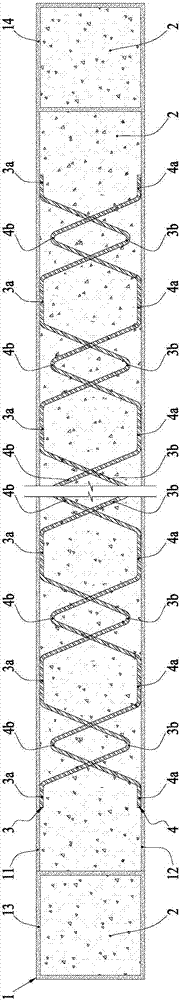
[0055] Such as image 3 As shown, the third embodiment of the present invention is based on the above-mentioned inventive concept, and adopts the following specific schemes for the first stirrup 3 and the second stirrup 4:

[0056] In the third embodiment, the first stirrup 3 and the second stirrup 4 are bent from a steel bar; and the welding section 3a of the first stirrup 3 and the welding section 4a of the second stirrup 4 are both Straight line, the protruding section 3b of the first stirrup 3 and the protruding section 4b of the second stirrup 4 are both V-shaped.


PUM


Abstract

The invention discloses an externally-wrapped steel plate reinforced concrete assembled shear wall and a construction method thereof. The exterior steel plate reinforced concrete assembled shear wall is provided with an externally-wrapped steel plate wall body, concrete and a plurality of stirrup pairs located in an inner cavity of the externally-wrapped steel plate wall body. Each stirrup pair comprises first stirrups and second stirrups, and the first stirrups and second stirrups are provided with welding sections and protruded sections equal in number; all the welding sections of the first stirrups are welded onto the inner side face of a first steel plate wall surface, and all the welding sections of the second stirrups are welded onto the inner side face of a second steel plate wall surface; all the protruded sections of the first stirrups correspond to the protruded sections of the second stirrups one to one, and part of an enclosed area of the protruded sections of the first stirrups is overlapped with part of an enclosed area of the protruded sections of the second stirrups in the vertical direction. According to the externally-wrapped steel plate reinforced concrete assembled shear wall and the construction method thereof, the opposite-pull effect between the two steel plate walls can be achieved through a few welding workloads, brittle failure of the concrete can be effectively restrained from occurring, earthquake-resistant ductility of the shear wall is greatly improved, and the externally-wrapped steel plate reinforced concrete assembled shear wall and the construction method thereof have the advantages that steel consumption is little, and manufacturing cost can be reduced.

Description

technical field [0001] The invention relates to a combined shear wall with outer-wrapped steel plate and reinforced concrete and a construction method thereof. Background technique [0002] Super high-rise building structures have higher and higher requirements for the strength and ductility of shear walls, and the higher the strength of concrete, the inherent brittleness of the material will bring adverse effects. The use of steel plate concrete composite shear walls can better solve this problem. a question. Through some structural measures, the outer steel plate can effectively restrain the high-strength concrete to prevent brittle failure, and the steel plate itself can greatly improve the ductility of the shear wall. [0003] In the existing steel plate concrete composite shear walls, the structural methods to strengthen the concrete restraint of the outer steel plate mainly include two forms: built-in stiffeners and tension bolts, supplemented by studs to strengthen t...

Claims


Application Information

Patent Timeline
Patent Type & Authority Applications(China)
IPC IPC(8): E04B2/86
CPCE04B2/86E04B2/8629
Inventor 张立平陈星徐卫梁志标何惠文洪磊
Owner ARCHITECTURAL DESIGN RES INST OF GUANGDONG PROVINCE
Why Eureka
Try Eureka