
Self-spacing double-T-shaped core-steel tube restriction anti-buckling support

An anti-buckling support and core technology, which is applied in the direction of earthquake resistance and building components, can solve the problems of increasing material consumption and man-hours, prone to buckling, and long construction period, so as to avoid excessive connection length, improve compressive bearing capacity, The effect of reducing project cost

Inactive Publication Date: 2013-12-11
NANJING UNIV OF TECH
View PDF5 Cites 0 Cited by
  • Summary
  • Abstract
  • Description
  • Claims
  • Application Information

AI Technical Summary

Problems solved by technology

This type of support is self-heavy, the construction process is complicated, the construction period is long, and it is difficult to disassemble and replace after the earthquake; moreover, when the anti-buckling support of the single core section is connected with the frame structure, eight splicing plates and two sets of bolts are required at each end, resulting in The external connection is long, the effective confinement area is short, and buckling is easy to occur; in addition, the limit card is easy to lose its limit effect gradually with the increase of external force, resulting in relative slippage between the restraint unit and the core unit, which affects the buckling-resistant support. mechanical properties; of course, the delamination material between the core unit and the constraint unit will increase the material consumption and man-hour
Later, although some scholars developed a double-sleeve double-core anti-buckling support, a core unit was inserted into each of the two sleeves of this support, and the ends of the combined two core units clamped the joint plate for connection, which solved the single-core anti-buckling support. The connection between the buckling support and the frame causes problems such as too long connection length, too many bolts, and short effective restraint area, but other problems have not been well resolved

Method used


Image

  • Self-spacing double-T-shaped core-steel tube restriction anti-buckling support
  • Self-spacing double-T-shaped core-steel tube restriction anti-buckling support

Examples


Embodiment Construction

[0023] The present invention will be further described below in conjunction with the accompanying drawings and specific embodiments.

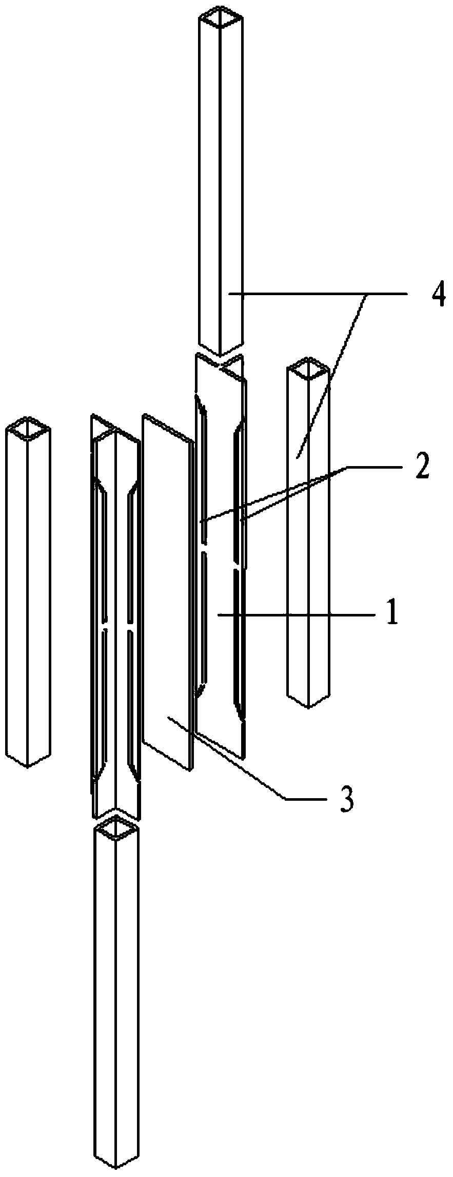
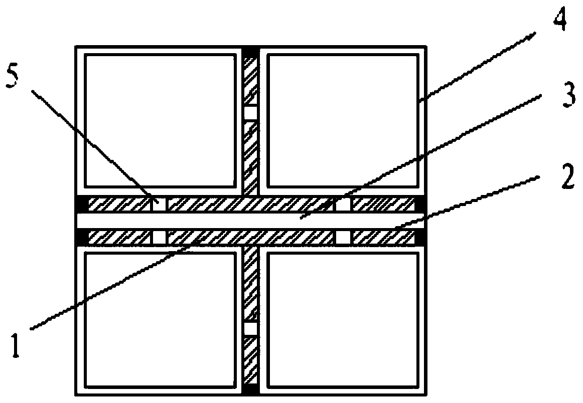
[0024] Such as figure 1 and 2 Shown: a self-limiting double T-shaped core-steel tube constrained buckling-resistant support, including the core force unit 1, the restraint mechanism and the side support unit 2;

[0025] The inner core stress unit is composed of two T-shaped steels with notches;

[0026] The constraining mechanism includes a steel plate constraining unit 3 and a steel pipe constraining unit 4, the steel plate constraining unit 3 is arranged in the middle of the two T-shaped steels, and the steel pipe constraining units 4 are four, respectively arranged in the two T-shaped steels. The four corners of the shaped steel;

[0027] The steel pipe constraining unit 4 includes two cross-section types of cold bending and hot rolling. The steel pipe constraining unit 4 includes two cross-sectional forms of square steel pipe and rectan...


PUM


Abstract

The invention discloses a self-spacing double-T-shaped core-steel tube restriction anti-buckling support which comprises a core stress unit, a restriction mechanism and a side stay unit, wherein the core stress unit is formed by combining two T-shaped steels with notches; the restriction mechanism comprises a steel plate restriction unit and four steel tube restriction units; the steel plate restriction unit is arranged between the two T-shaped steels; the four steel tube restriction units are respectively arranged at four corners of the two T-shaped steels; the side stay unit is arranged on the side surface of the core stress unit; the shape of the side stay unit is matched with that of the notch of the T-shaped steel; and a clearance is left between the side stay unit and the core stress unit. The restriction mechanism effectively prevents the core stress unit from stressing and buckling, and can yield without buckling when being stressed, thereby enhancing the pressure resisting bearing capacity; and the pull and pressure bearing capacities are equal.

Description

technical field [0001] The invention relates to the technical field of a new type of building structure, in particular to a self-limiting double T-shaped inner core-steel tube constrained anti-buckling support. Background technique [0002] The traditional anti-buckling bracing is generally composed of a single core unit composed of cross-shaped or in-line steel plates, delamination materials, limit cards, and steel tube concrete restraint units. This type of support is self-heavy, the construction process is complicated, the construction period is long, and it is difficult to disassemble and replace after the earthquake; moreover, when the anti-buckling support of the single core section is connected with the frame structure, eight splicing plates and two sets of bolts are required at each end, resulting in The external connection is long, the effective confinement area is short, and buckling is easy to occur; in addition, the limit card is easy to lose its limit effect gra...

Claims


Application Information

Patent Timeline
Patent Type & Authority Applications(China)
IPC IPC(8): E04B1/98
Inventor 郑廷银喻圣洁杨菊
Owner NANJING UNIV OF TECH
Learn More