Elbow pipe and method for producing an elbow pipe

A pipe bending and pipe body technology, applied in the field of pipe bending and manufacturing of pipe bends, can solve the problems of time-consuming and cost-effective

Inactive Publication Date: 2008-01-16
ESSER WERKE
View PDF1 Cites 10 Cited by
  • Summary
  • Abstract
  • Description
  • Claims
  • Application Information

AI Technical Summary

Problems solved by technology

This is time consuming and costly
The hole creates a potential weak point with respect to the thin-walled outer bend

Method used


Image

  • Elbow pipe and method for producing an elbow pipe
  • Elbow pipe and method for producing an elbow pipe
  • Elbow pipe and method for producing an elbow pipe

Examples


Embodiment Construction

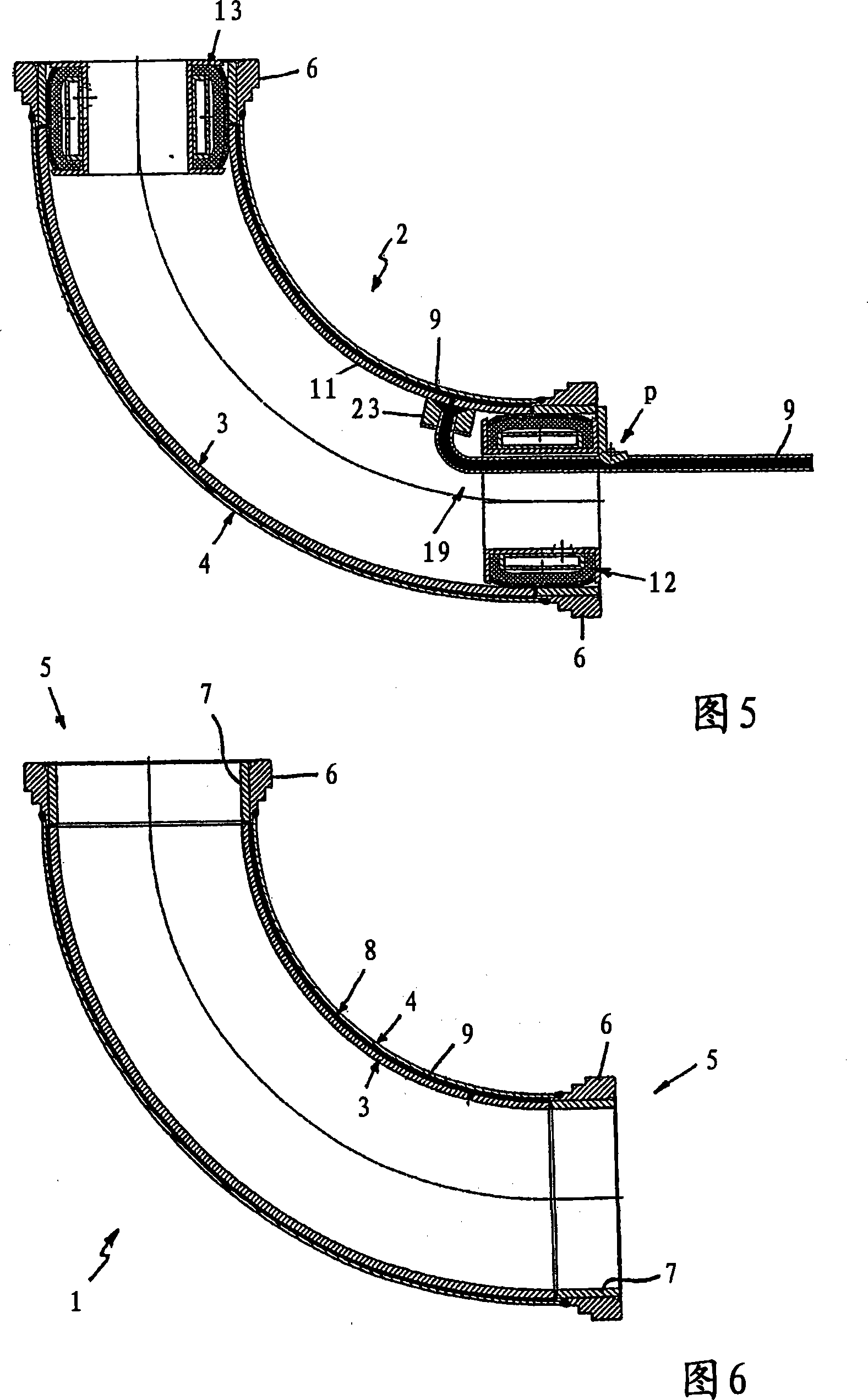
[0014] The resulting bend is shown in Figure 6. The bend 1 is used inside pipes for the fluid transport of solids, for example in the distribution boom of an automatic concrete pump.

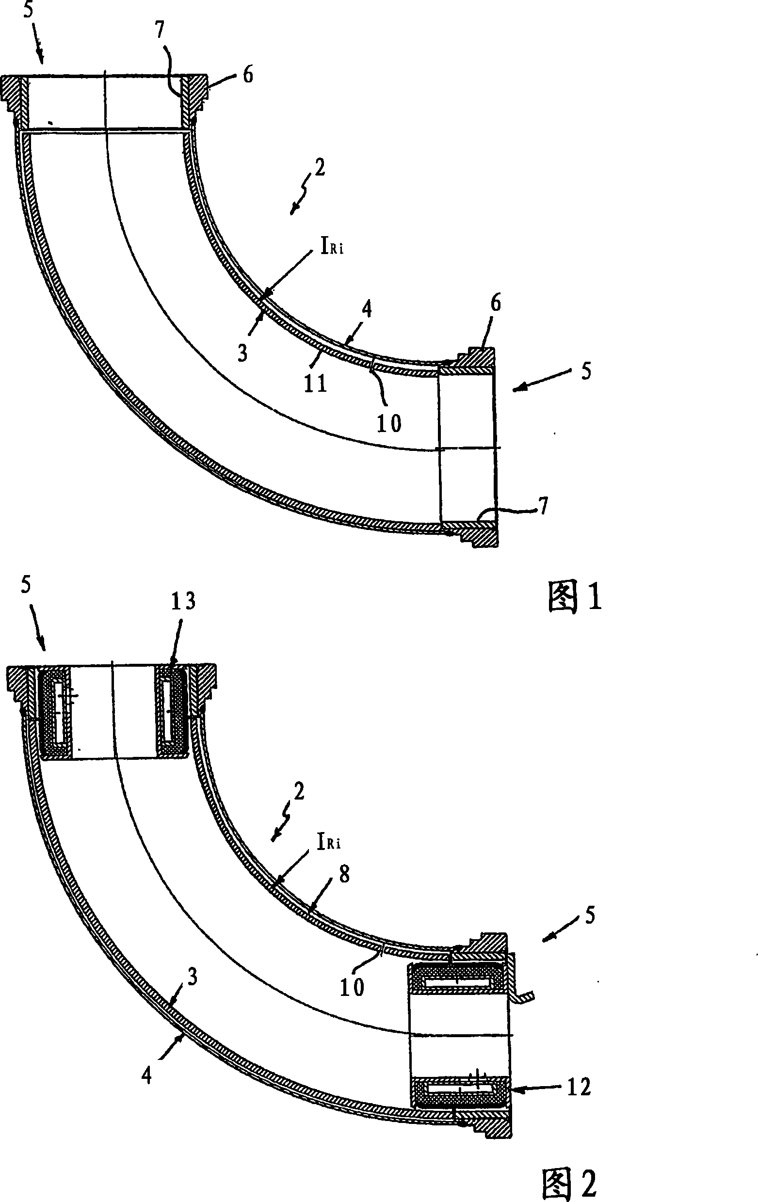
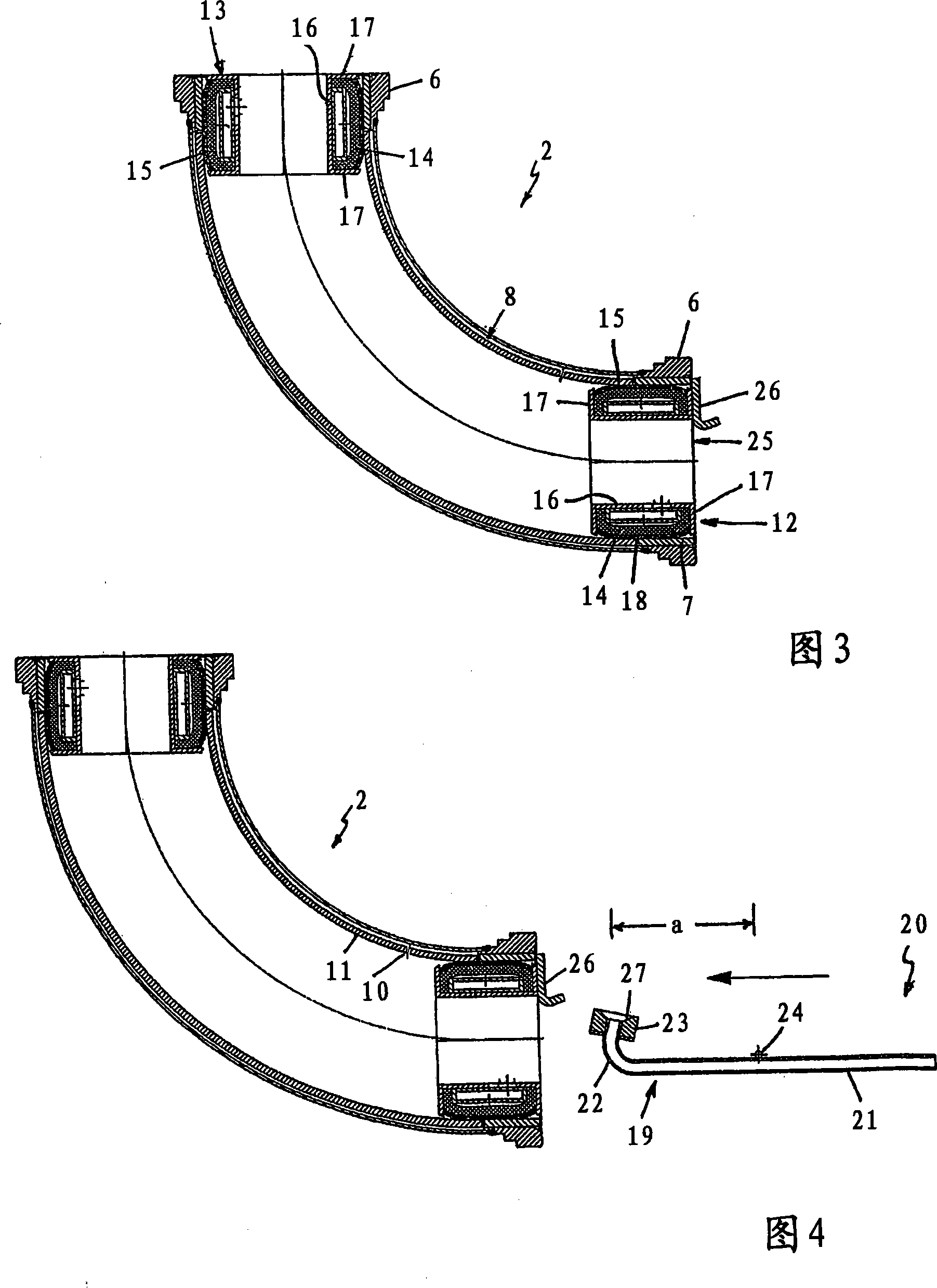
[0015] As can be seen in particular in FIG. 2 , the pipe bend 1 has a double-layer pipe body 2 comprising a highly wear-resistant hardened inner bend 3 and a pressure-resistant weldable outer bend 4 . A coupling flange 6 is attached to each pipe end 5 of the pipe body 2 . The coupling flanges 6 each surround an inner wear ring 7 and are welded to the outer bend 4 .

[0016] The annular space 8 between the inner bend 3 and the outer bend 4 is filled with concrete as filler 9 . In order to introduce the filler 9, the inner radius I of the inner elbow 3 Ri A filling opening 10 is arranged on it, which passes transversely through the wall 11 of the inner bend 3 (see FIGS. 1 to 5 here).

[0017] To produce the pipe bend 1 , the inner pipe bend 3 , the outer pipe bend 4 and the coupling flange 6 ,...


PUM


Abstract

The invention relates to an elbow pipe (1) for a pipe tract used in the fluidic transport of solids and to a method for producing said pipe. The elbow pipe (1) comprises a double-layer pipe body (2) consisting of an internal elbow pipe (3) and an external elbow pipe (4). A coupling collar (6) is fixed to each end (5) of the pipe body (2). The annular gap (8) between the internal elbow pipe (3) and the external elbow pipe (4) is filled with concrete as the filler (9). The annular gap (8) is filled via a fill opening (10) in the wall (11) of the internal elbow pipe (3), the opening running transversally through said wall and being situated on the inner radius lRi of the internal elbow pipe (3). To fill said gap, centring aids (12, 13) are introduced into the ends of the pipe body (2) and the internal elbow pipe (3) and external elbow pipe (4) are positioned in relation to one another, by the inflation of the centring aids (12, 13). The filling gun (19) of a filling device (20) is then placed against the fill opening (10) in the wall (11) of the internal elbow pipe (3) and the annular gap (8) is filled with the filler (9).

Description

technical field [0001] The invention relates to a pipe bend for a pipe for fluidly conveying solids and to a method for producing such a pipe bend. Background technique [0002] DE 101 43 290 A1 discloses a pipe bend with a double-layer pipe body, which consists of an inner bend and an outer bend. The annular space between the inner bend and the outer bend can be filled with a packing as a pressure compensation layer. For this purpose a hole is machined into the wall of the outer bend, through which the gap between the inner bend and the outer bend is filled. The hole is then cleaned, welded, ground and polished. This is time consuming and costly. This hole presents a potential weak point with respect to the thin-walled outer bend. Contents of the invention [0003] Proceeding from the prior art, the object of the present invention is to realize a pipe bend which is improved in terms of production technology and safety technology and to propose a method for the product...

Claims


Application Information

Patent Timeline
Patent Type & Authority Applications(China)
IPC IPC(8): B65G53/52F16L43/00F16L9/18F16L57/06
CPCB65G2207/48F16L9/153F16L43/001F16L43/007B65G53/523F16L57/06Y10T29/49444F16L9/12F16L58/06
Inventor A·埃塞尔
Owner ESSER WERKE
Why Eureka
Try Eureka