
Flexible protective cover apparatus of cutter

A technology of protective cover and cutting machine, which is applied in the attachments of sawing machines, metal sawing equipment, maintenance and safety accessories, etc. Accuracy, reasonable and simple structure design, and the effect of improving the overall mechanical performance

Inactive Publication Date: 2009-07-29
胡桂强
View PDF5 Cites 0 Cited by
  • Summary
  • Abstract
  • Description
  • Claims
  • Application Information

AI Technical Summary

Problems solved by technology

The traditional electric cutting machine has no movable protective cover, so there are some unsafe hidden dangers. For this reason, someone has designed an electric cutting machine with a movable protective cover.
For example, the Chinese patent No. 02266104.2 "Mobile protective cover structure for electric cutting machine", it includes a fixed cover with one end movably hinged on the rocker arm, the lower opening of the fixed cover is movably fixed with the movable protective cover coaxial core, and the movable protective cover A connecting rod mechanism is connected between the cover and the end of the rocker arm, which is characterized in that one end of the short connecting rod is articulated with the end of the rocker arm, the other end is articulated with the connecting rod, and the other end of the connecting rod is articulated with the movable The protective cover is movable and hinged, and there is a track groove in the middle of the connecting rod, and the track groove cooperates with the positioning pin on the inner side of the fixed cover. This also represents a design idea of ​​using a linkage mechanism to control the opening and closing of the movable protective cover. Although it has a simple structure, low manufacturing cost, and is easy to implement, there are some flaws in the actual use that cannot be overcome, such as relatively high requirements for the processing and assembly of connecting rods and track grooves, and slight processing errors or installation errors. , it is easy to cause a dead point, so that the control of the linkage mechanism is inflexible, not smooth, or even stuck, which is easy to cause and cause safety accidents in production, and once these shortcomings are formed, it is difficult to self-correct by adjusting the installation position , so we need to develop a new cutting machine movable shield device to overcome the above-mentioned deficiencies
Although the patent No. is 02215672.0 Chinese patent "Electric Cutting Machine" also reported a protective cover transmission mechanism in which the gear and the upper rack of the connecting rod are meshed and connected, but because its transmission mechanism is mainly in the inside of the protective cover, it cannot be carried out. Observation, it is difficult to eliminate the processing error through the meshing position of the rack and the gear, the adjustment operation is difficult, and the maintenance is also difficult. Moreover, the rack is directly formed on the slender connecting rod, and the connecting rod is set inside the protective cover, resulting in The processing technology of the rack is relatively high, and the assembly and disassembly are not convenient enough, which is not convenient for actual production assembly and future maintenance. Therefore, the design needs to be further improved

Method used


Image

  • Flexible protective cover apparatus of cutter
  • Flexible protective cover apparatus of cutter
  • Flexible protective cover apparatus of cutter

Examples


Embodiment Construction

[0019] The present invention will be further described in detail below in conjunction with the accompanying drawings and embodiments.

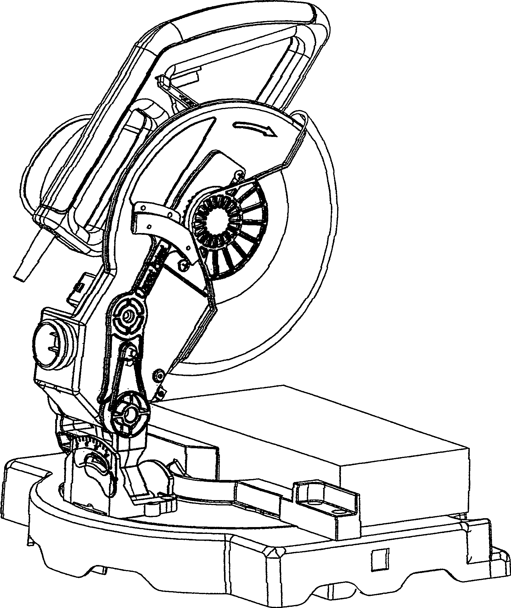
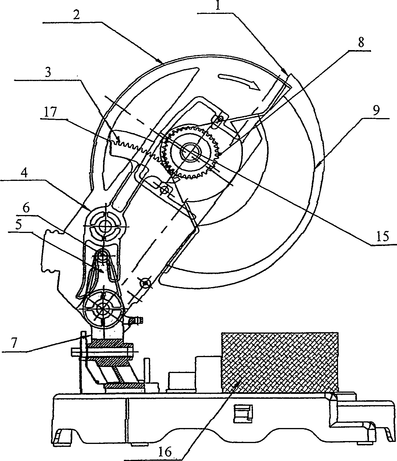
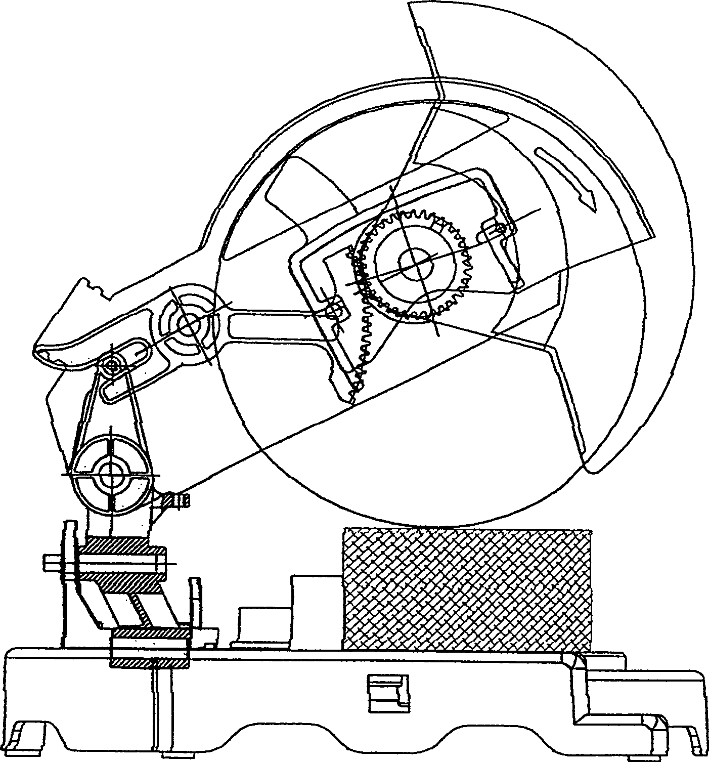
[0020] As shown in the figure, the movable protective cover device of this kind of cutting machine includes a fixed protective cover 2 fixed on the cutting head of the cutting machine, a movable protective cover 1, a pull rod 4, a gear 8, a spring, and a fixed plate 10. Main parts such as, fixed protective cover 2 is connected with rocking arm 7 on the cutting machine by rotating shaft 15, and the lower end of rocking arm 7 is connected and fixed with machine base position. The movable protective cover 1 is relatively engaged with the fixed protective cover 2 from bottom to top, and is rotatably connected to the fixed protective cover 2 at the same time. Connect and fix on the fixed plate 10 through the insert 13 and the lock nut 12 and the washer 11, and the fixed plate 10 is fixed on the fixed protective cover 2 by fasteners such as screws, ...


PUM


Abstract

A movable protective cover device for a cutting machine, wherein the cutting machine includes a fixed protective cover and a movable protective cover fixed on the cutting head, the movable protective cover engages with the fixed protective cover from bottom to top, and is rotatably connected to the On the fixed protective cover, the movable protective cover is provided with a gear at its rotating connection part, which is characterized in that a rotatable pull rod is connected and fixed on the outer side of the fixed protective cover at the same time, and the upper end of the pull rod is formed with a rack. The rack is meshed with the gear, and the lower end of the pull rod has an open slot, which is plugged and matched with the positioning pin on the rocker arm. The processing error makes the opening and closing of the movable protective cover flexible, avoiding dead spots, stuck positions and out-of-place phenomena, improving the safety performance of the cutting machine, and the maintenance is also very convenient. It is suitable for popularization and use on the cutting machine.

Description

technical field [0001] The invention relates to the technical field of a movable protective cover device for a cutting machine. Background technique [0002] With the development of the building materials industry, electric cutting machines among electric tools are widely used to cut various metal pipes, angle steel, channel steel and various stone plates, so there is a huge market for electric cutting machines, so there are scientific and technological personnel Developed various electric cutting machines. The traditional electric cutting machine does not have a movable protective cover, so there are some unsafe hidden dangers. For this reason, someone has designed an electric cutting machine with a movable protective cover. For example, the Chinese patent No. 02266104.2 "Mobile protective cover structure for electric cutting machine", it includes a fixed cover with one end movably hinged on the rocker arm, the lower opening of the fixed cover is movably fixed with the mov...

Claims


Application Information

Patent Timeline
IPC IPC(8): B23Q11/08B23D59/00
Inventor 胡桂强
Owner 胡桂强
Learn More