Resin pallet
A technology of pallets and resins, applied in rigid containers, containers, packaging, etc., can solve problems such as the inability to add unit components and the limitation of dimensional freedom
- Summary
- Abstract
- Description
- Claims
- Application Information
AI Technical Summary
Problems solved by technology
Method used
Image
Examples
no. 1 Embodiment approach
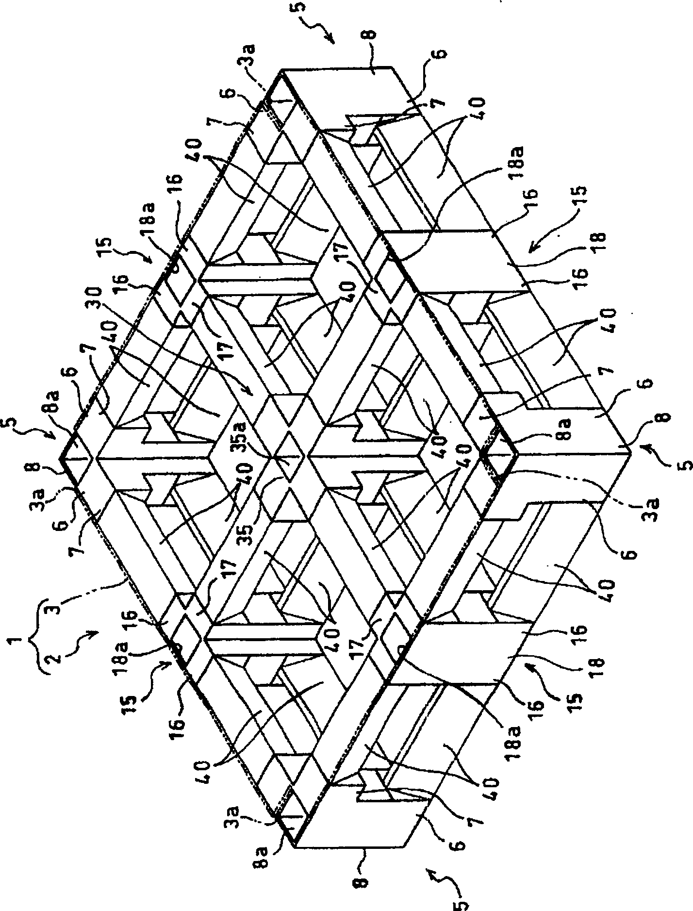
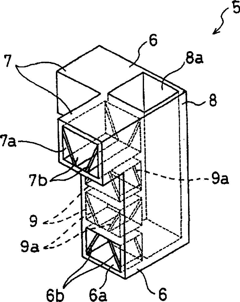
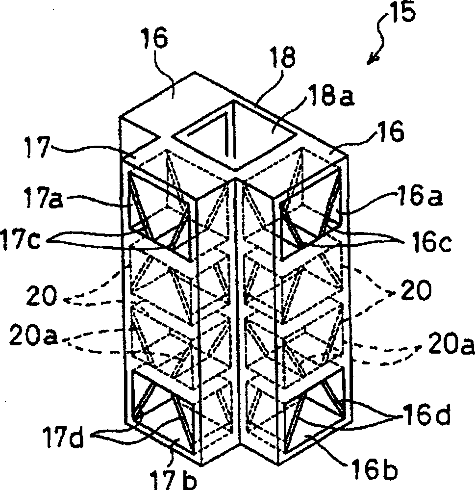
[0096] figure 1 It is a perspective view which shows the whole structure of the resin pallet which concerns on 1st Embodiment of this invention. figure 1The shown resin pallet 1 has four L-shaped blocks 5 having an L-shaped planar shape, four T-shaped blocks 15 having a T-shaped planar shape, and one X-shaped block 30 having an X-shaped planar shape. Among these three kinds of multiple blocks 5, 15, 30, four L-shaped blocks 5 are respectively arranged at the four corners, T-shaped blocks 15 are respectively arranged in the middle between the L-shaped blocks 5, and in the center of the resin pallet 1 The X-shaped block 30 is arranged on the upper part, and each block 5, 15, 30 is connected with the connecting member 40 to form the skeleton part 2 of the resin pallet 1. Then, the upper surface (one plane) of the covered skeleton part 2 is covered by an adhesive or the like. The resin-made flat plate 3 arranged ground is fixed on the skeleton part 2, and the resin pallet 1 is ...
no. 2 Embodiment approach
[0118] Next, assemble 4 L-shaped blocks 5, 6 T-shaped blocks 15, and 2 X-shaped blocks 30 with a plurality of connecting members 40, and then subdivide the skeleton part 2 of the above-mentioned resin pallet 1 into grids. The resin pallet 51 will be described. The above-mentioned components are denoted by the same symbols and their descriptions are omitted.
[0119] Image 6 It is a schematic plan view of the resin pallet of 2nd Embodiment. exist Image 6 The illustrated connecting member 40 is shown with crosshatching, so that it can be understood that the openings 6a, 7a, 16a, 7a, 16a, 16b, 17a, 17b, 31a, 32a, 33a, 34a in the position of the connecting member 40.
[0120] like Image 6 As shown, in the resin pallet 51, the L-shaped blocks 5 are arranged at the four corners, and the connecting members 40 are respectively inserted in the openings 6a, 7a of the protruding parts 6 of the L-shaped blocks 5, and the L-shaped blocks 5 are connected. At positions where the con...
no. 3 Embodiment approach
[0126] Next, assemble the above-mentioned 4 L-shaped blocks 5, 8 T-shaped blocks 15, 4 X-shaped blocks 30, and a plurality of connecting members 40, and then subdivide the skeleton part 52 of the above-mentioned resin pallet 51 The resin pallet 61 in grid form is demonstrated. The above-mentioned components are denoted by the same symbols and their descriptions are omitted.
[0127] Figure 7 It is a schematic plan view of the resin pallet of 3rd Embodiment. in such as Figure 7 The connecting member 40 shown is indicated by adding hatching symbols, and it can be seen that the openings 6a, 7a of the protrusions 6, 16, 17, 31, 32 of the blocks 5, 15, 30 are inserted into the openings 6a, 7a. , 16a, 16b, 17a, 17b, 31a, 32a, 33a, 34a the position of the connecting member 40.
[0128] like Figure 7 As shown, in the resin pallet 61, the L-shaped blocks 5 are arranged at the four corners, the connecting members 40 are respectively inserted into the openings 6a, 7a of the protr...
PUM
 Abstract
Description
Claims
Application Information
 - R&D
- Intellectual Property
- Life Sciences
- Materials
- Tech Scout
- Unparalleled Data Quality
- Higher Quality Content
- 60% Fewer Hallucinations
Browse by: Latest US Patents, China's latest patents, Technical Efficacy Thesaurus, Application Domain, Technology Topic, Popular Technical Reports.
© 2025 PatSnap. All rights reserved.Legal|Privacy policy|Modern Slavery Act Transparency Statement|Sitemap|About US| Contact US: help@patsnap.com


