Siphon for toilets

A technology for siphons and toilets, applied in the field of siphons, which can solve problems such as parts damage, loss, and inability to complete functions

Inactive Publication Date: 2009-08-12
OMP SNC
View PDF4 Cites 0 Cited by
  • Summary
  • Abstract
  • Description
  • Claims
  • Application Information

AI Technical Summary

Problems solved by technology

[0005] For this reason, conventional siphons have many disadvantages, mainly due to the fact that they are produced and sold as separate elements, which are joined together when installing the siphon
[0006] In this way, if the volumes for transport and sale are to be reduced, the production and installation costs are increased due to the many necessary parts (which, in addition to the tubular elements, also include the connection elements between the two tubular elements)
[0007] It is also possible that when assembling the siphon some parts are damaged or missing, in which case the siphon will not be able to function to its optimum ability to transmit flushing water or not at all

Method used


Image

  • Siphon for toilets
  • Siphon for toilets

Examples


Embodiment Construction

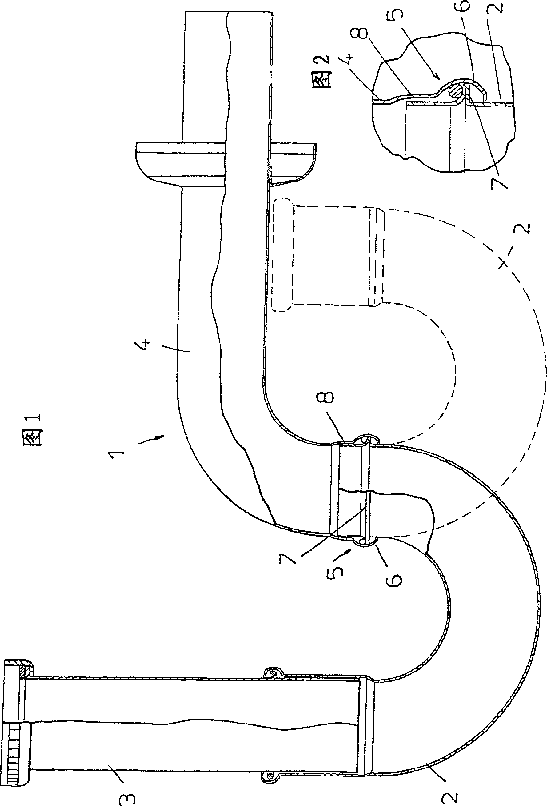
[0022] Referring to the attached drawings, a siphon for a toilet shown in the figures is indicated with the reference numeral 1 throughout.

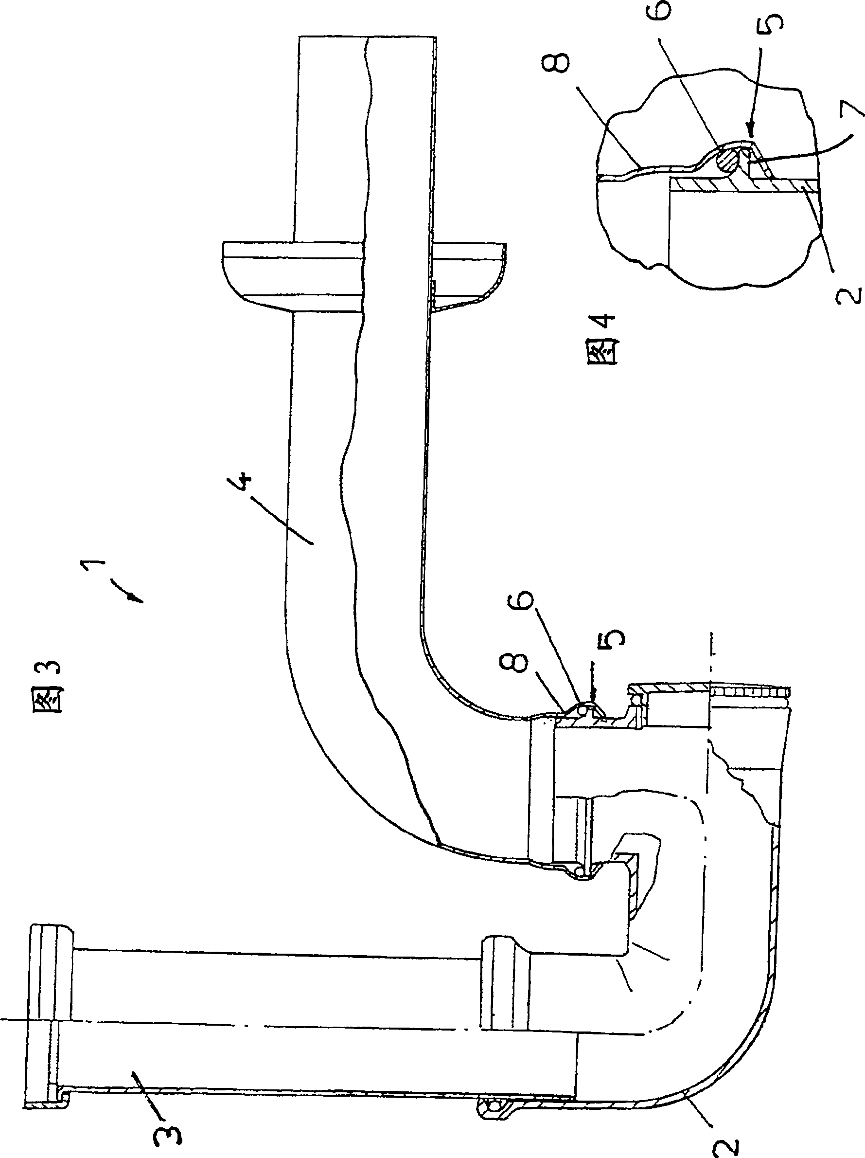
[0023] The siphon 1 comprises a first tubular element 2 for connection to the toilet drain 3 and a second tubular element 4 for connection to the wall drain.

[0024] Advantageously, the first tubular element 2 and the second tubular element 4 are connected together watertight in a rotational manner, thereby enabling a small volume transfer position (indicated by dashed lines in FIG. 1 ) and an installation position in which the tubular elements 2, 4 extend (indicated by a continuous line in Figure 1) between rotations.

[0025] The second tubular element 4 has at one of its ends at least one circular base 5 into which one end of the first tubular element is inserted and vice versa, that is, the circular base can be A seat 5 is provided at the end of the first tubular element 2 .

[0026] The circular base 5 comprises a first widening ...


PUM


Abstract

A siphon for a toilet comprising a first tubular element (2) for connection to the toilet drain and a second tubular element (4) for connection to the wall drain. The first tubular element and the second tubular element are rotationally coupled together watertight so as to be rotatable between a small volume transport position and an installed position in which the tubular element is extended.

Description

technical field [0001] The invention relates to a siphon for a toilet. Background technique [0002] All toilets are known to have siphons that prevent backflow of odors or whatever. [0003] In particular, conventional siphons consist of one tubular element connected to the outlet pipe of the toilet and another tubular element connected to the drain pipe of the wall. [0004] The aforementioned two tubular elements are separate from each other and are connected when the siphon is installed. [0005] For this reason, conventional siphons suffer from a number of disadvantages, mainly due to the fact that they are produced and sold as separate elements, which are joined together when the siphon is installed. [0006] In this way, if the volumes for transport and sale are to be reduced, the production and installation costs are increased due to the many necessary parts (which, in addition to the tubular elements, also include the connection elements between the two tubular el...

Claims


Application Information

Patent Timeline
Patent Type & Authority Patents(China)
IPC IPC(8): E03D11/18E03C1/284F16L27/08F16L43/00
CPCF16L43/00F16L27/08E03D11/18E03C1/284E03D11/02
Inventor 瑟乔·帕索蒂
Owner OMP SNC
Why Eureka
Try Eureka