Seal moving device for remote network seal machine

A remote network and mobile device technology, applied in the field of seal mobile devices, can solve the problems of time delay, inconvenient operation, and invalid documents, and achieve the effect of convenient operation.

Inactive Publication Date: 2009-08-19
张立安
View PDF9 Cites 0 Cited by
  • Summary
  • Abstract
  • Description
  • Claims
  • Application Information

AI Technical Summary

Problems solved by technology

At present, the process of affixing a seal mostly adopts the traditional manual method of stamping with force. This traditional method of affixing the seal is likely to cause the seal to be unclear due to uneven force and uneven distribution of the ink pad, which makes the identification of the seal troublesome and often needs to be reprinted. Affix a seal or invalidate the stamped document; in addition, manual affixing makes the control and management of the seal troublesome, and the seal holder and manager need to carry the seal with him or lock the seal in the area under his control. When the administrator is not next to the seal, but needs to affix the seal on the document as soon as possible, it will cause time delays and even cause economic losses; and if the seal holder and the administrator hand over the seal to other personnel in advance, It is also difficult to effectively control the seal. Once certain documents are stamped without authorization, it will cause great economic losses to the owner of the seal.
[0003] At present, there is also a stamping machine with uniform force and clear seal image on the market. The Chinese patent announcement number is CN 2351283Y, and the announcement date is December 1, 1999. Disclosed a kind of such stamping machine, its shortcoming is: stamping process is still manual operation, can't carry out effective management and control to stamp stamping authority and usage situation; Its stamp can only move vertically up and down, The position of the plane cannot be moved back and forth, left and right, so it can only be stamped on documents with a fixed size and a fixed position of the stamp. It cannot stamp a variety of documents and documents with different stamping positions. Its application range is small, and there are many stamps. , Enterprises and departments with many stamped documents need multiple stamping machines
[0004] Therefore, the existing technology has the following deficiencies: the seal position cannot be adjusted by moving back and forth, and the operation is inconvenient

Method used


Image

  • Seal moving device for remote network seal machine
  • Seal moving device for remote network seal machine
  • Seal moving device for remote network seal machine

Examples


Embodiment 1

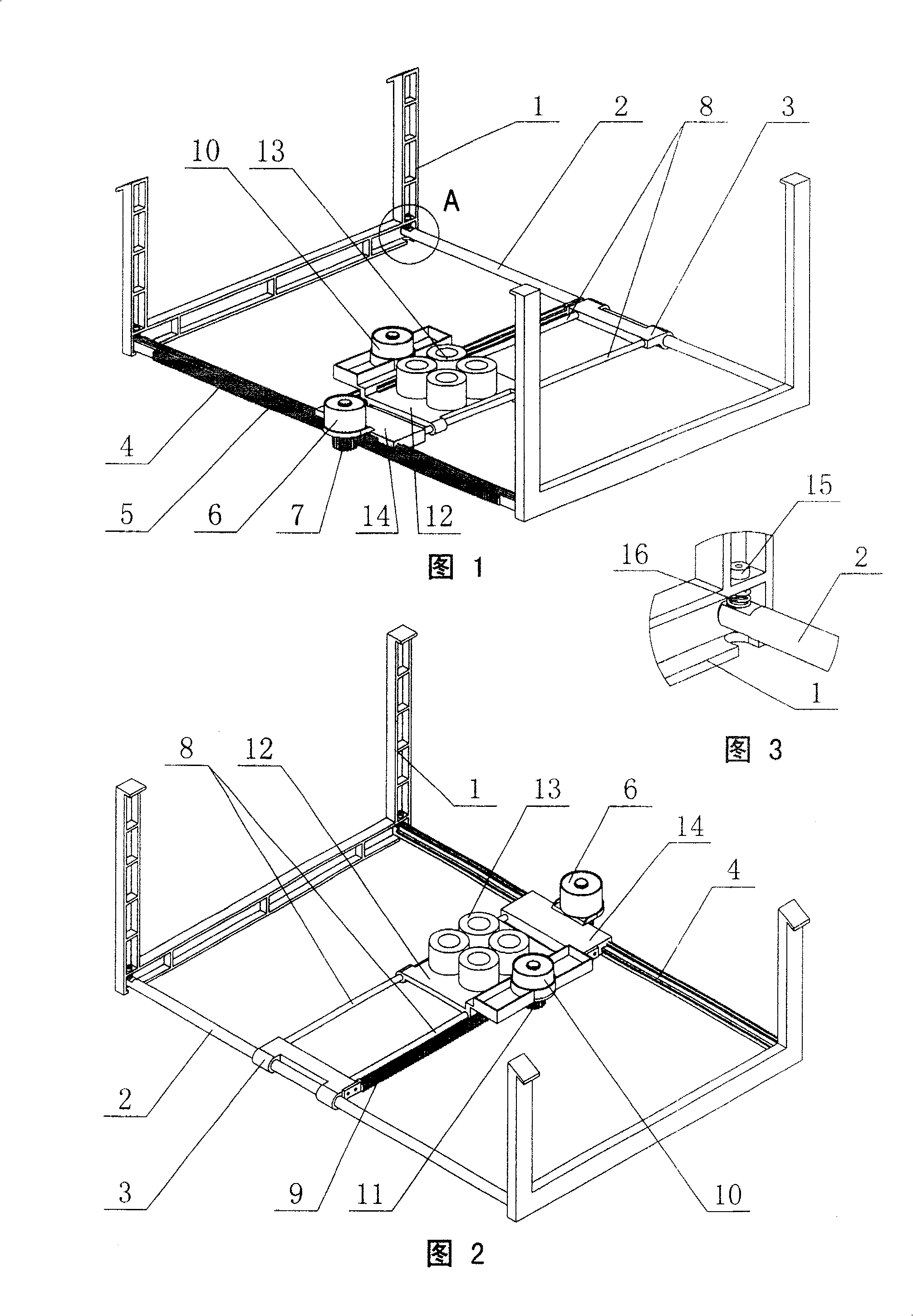
[0025] Such as figure 1 , figure 2 , image 3 As shown, the present invention includes a fixed support 1, a longitudinal drive mechanism, a transverse drive mechanism, and a mobile support 12. The seal holding device 13 is fixed on the mobile support 12, and the longitudinal drive mechanism is connected to the fixed support 1. The longitudinal drive mechanism includes a longitudinal motor 6, an I longitudinal guide rail 2, and an II longitudinal guide rail 4. The I longitudinal guide rail 2, the II longitudinal guide rail 4 are parallel to each other and connected to the fixed bracket 1, and the longitudinal motor 6 The output shaft is fixedly connected to the I gear 7, the I longitudinal guide rail 2 is smooth and cylindrical, and the II longitudinal guide rail 4 is provided with a guide groove and an I rack 5.

[0026] The transverse drive mechanism includes a transverse motor 10 and two smooth cylindrical transverse guides 8 parallel to each other. The ends of the two transve...

Embodiment 2

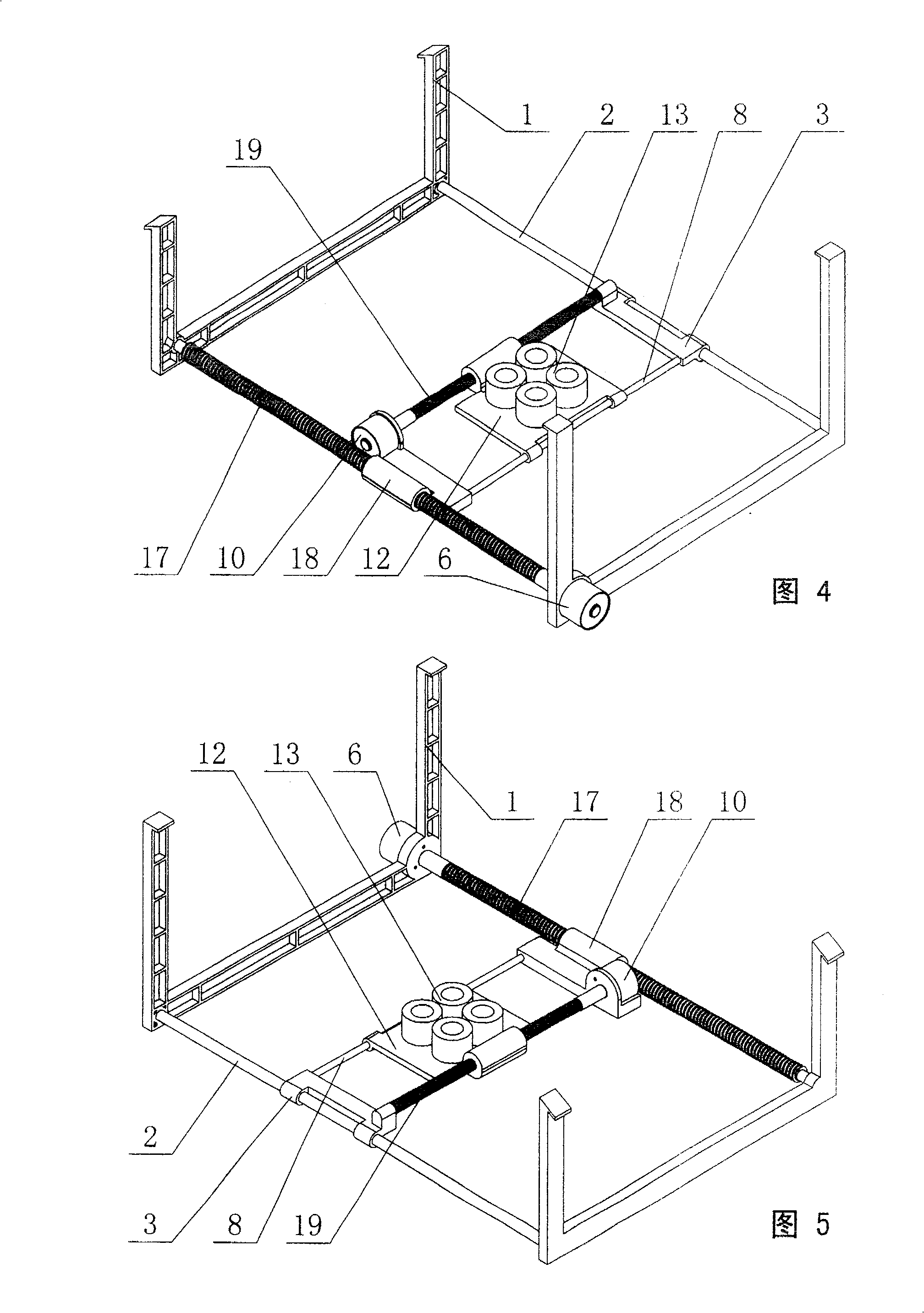
[0030] Such as Figure 4 , Figure 5 As shown, this embodiment includes a fixed bracket 1, a longitudinal drive mechanism, a lateral drive mechanism, and a mobile bracket 12. The seal holding device 13 is fixed on the mobile bracket 12, and the longitudinal drive mechanism is connected to the fixed bracket 1. , The longitudinal drive mechanism includes a longitudinal motor 6, an I longitudinal guide rail 2, a longitudinal lead screw 17, the I longitudinal guide rail 2, the longitudinal lead screw 17 are parallel to each other and connected to the fixed support 1, the longitudinal motor 6 is fixedly connected to the fixed support 1, and the output shaft of the longitudinal motor 6 is fixedly connected to the longitudinal screw 17.

[0031]The transverse drive mechanism includes a transverse motor 10, a transverse guide 8, and a transverse screw 19. The I longitudinal guide 2 and the transverse guide 8 are both smooth and cylindrical, and the transverse guide 8 and the transverse sc...

Embodiment 3

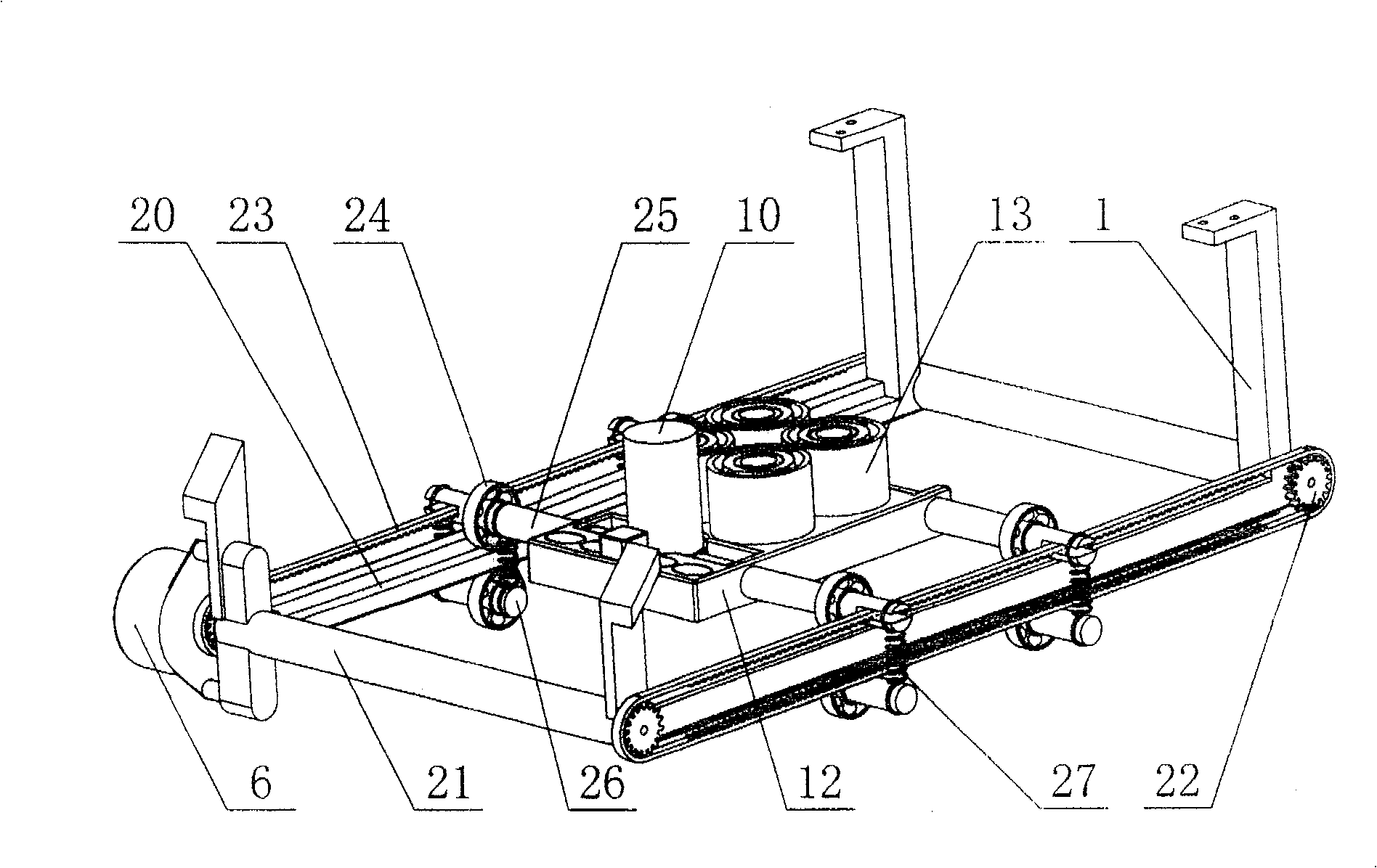
[0034] Such as Figure 6 , Figure 7 , Figure 8 As shown, this embodiment includes a fixed bracket 1, a longitudinal drive mechanism, a lateral drive mechanism, and a mobile bracket 12. The seal holding device 13 is fixed on the mobile bracket 12, and the longitudinal drive mechanism is connected to the fixed bracket 1. The fixed bracket 1 includes two longitudinal beams 20, two transverse beams 21, the longitudinal drive mechanism includes a longitudinal motor 6, two ring gear belts 23 parallel to the longitudinal beam 20, four III gears 22, two There are two main shafts 25 and four secondary shafts 26. The shaft of the III gear 22 is fixed at both ends of the beam 21, the longitudinal motor 6 is fixedly connected to the fixed support 1, and the output shaft of the longitudinal motor 6 is connected to one The III gear 22 is fixedly connected, the two main shafts 25 are arranged in parallel, each of the main shafts 25 has a notch at both ends, and the notch is provided with a gear...


PUM


Abstract

The present invention discloses a kind of seal moving device for remote network seal machine, and aims at providing one kind of seal moving device capable of shifting the seal horizontally for remote network seal machine. The seal moving device includes fixing support, longitudinal driving mechanism, transverse driving mechanism, movable rack and seal holder fixed on the movable rack. The longitudinal driving mechanism connected to the fixing support includes a longitudinal motor; and the transverse driving mechanism includes a transverse motor. The present invention may be applied widely in seal management of different industry.

Description

Technical field [0001] The invention relates to a seal moving device of a remote network seal verification machine. Background technique [0002] In daily social and economic activities, many contracts, bills and other documents need to be stamped with various seals. At present, most of the process of stamping is to use the traditional manual stamping method. This traditional stamping method is prone to unclear stamps due to uneven force and uneven distribution of the ink pad, which makes the identification of the stamps troublesome and often needs to be renewed. Stamping or making the stamped documents invalid; in addition, manual stamping makes the control and management of the seal troublesome. The owner and manager of the seal need to carry the seal with them or lock the seal in the area under their control. In this way, once the seal is held When the administrator is not next to the seal, but needs to stamp the document as soon as possible, it will cause time delays and even...

Claims


Application Information

Patent Timeline
Patent Type & Authority Patents(China)
IPC IPC(8): B41K3/00B41L13/00
Inventor 张立安
Owner 张立安
Why Eureka
Try Eureka