CO-containing raw gas conversion and heat recovery method

A raw material gas and shift reaction technology, applied in steam generation methods, chemical instruments and methods, climate sustainability, etc., can solve problems affecting the long-term stable operation of the transform unit, difficulty in raising the temperature of the raw gas, and small temperature differences in the raw gas, etc. problems, to achieve the effect of improving waste heat recovery efficiency, saving equipment investment and land occupation, and reducing system resistance

Active Publication Date: 2020-06-12
HAISO TECH
View PDF13 Cites 0 Cited by
  • Summary
  • Abstract
  • Description
  • Claims
  • Application Information

AI Technical Summary

Problems solved by technology

[0004] The isothermal shift process, or the combination of isothermal and adiabatic process, is that the crude gas enters the isothermal shift furnace for shift reaction after exchanging heat with the shift gas to increase the temperature, and removes most of the heat generated by the shift reaction through the by-product steam, and exits the shift furnace. The shifted gas passes through the steam generator to by-produce low-pressure steam and the desalted water heater is used to heat the low-temperature desalted water to recover the waste heat of the shifted gas, the shifted gas is cooled by the water cooler with circulating water, and finally the NH in the shifted gas is washed out through the ammonia scrubber 3 ; In the process of waste heat recovery and cooling of the above-mentioned shift gas, condensate is produced at each step, which needs to be separated by a separate separator; in actual operation, due to the low temperature at the outlet of the isothermal shift furnace and the small temperature difference with the crude gas, heat exchange is used It is difficult to increase the temperature of crude gas to the temperature required by the reaction
[0005] For example, "Isothermal Transformation System for Removing CO from Feed Gas" disclosed in the Chinese invention patent application with application number 201520522410.2 and "A water transfer system for energy-saving deep conversion of by-product high-grade steam" disclosed in Chinese invention patent application with application number 201210185731.9 Heat transfer process", both of these two processes use a water transfer heat type isothermal transfer furnace to control the reaction temperature, and the crude gas is heated by a heat exchanger. Due to the small heat transfer temperature difference, the heat transfer area is very large, and the actual operation It is impossible to increase the temperature of the raw material gas in the later stage of catalyst use; moreover, the dust contained in the raw gas can easily block the heat exchanger, affecting the long-term stable operation of the conversion unit; The gas-liquid separator is used to separate the ammonia in the converted gas, and the ammonia washing tower is installed separately to wash it. Not only the equipment is multi-process and the process is long, but also the piping is complicated and the system cost is high.

Method used


Image

  • CO-containing raw gas conversion and heat recovery method
  • CO-containing raw gas conversion and heat recovery method
  • CO-containing raw gas conversion and heat recovery method

Examples


Embodiment 1

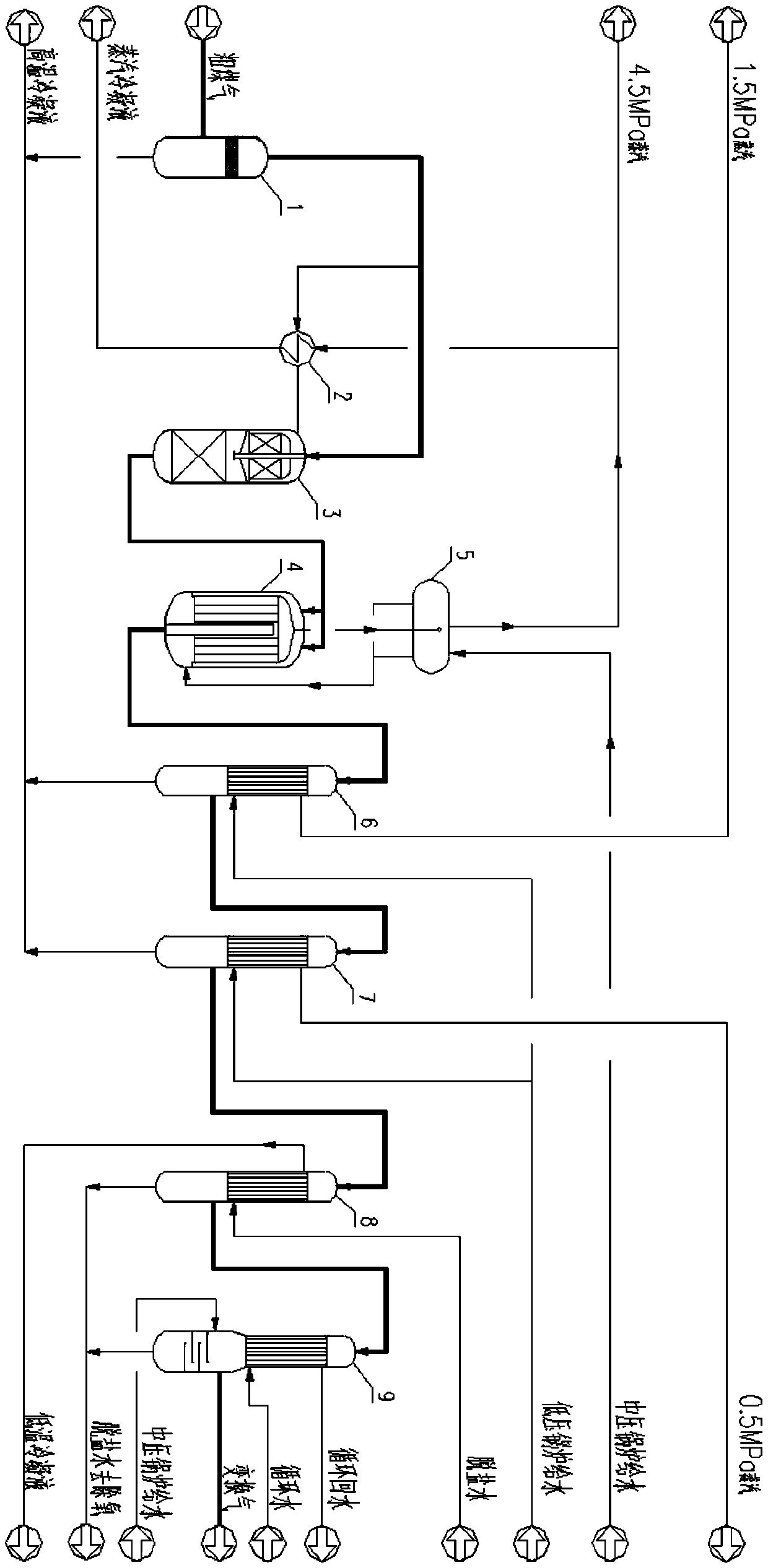
[0041] Such as figure 2 As shown, the crude gas from the coal-water slurry gasification device (pressure is 6.3MPaG, temperature 240 ℃), after the liquid water is separated by the raw material gas separator 1, it is divided into two shares, and one of which is about 25% of the crude gas through the raw gas The preheater 2 is heated to 260°C and enters the upper section of the self-heating purification furnace 3. After the reaction, it is fully mixed with another about 75% of the crude gas that directly enters the center tube, and the temperature is about 275°C. , and then enter the temperature-controlled shift furnace 4 to carry out the shift reaction. The raw gas entering the temperature-controlled shift furnace, under the action of the inter-tube shift catalyst, CO and H 2 The shift reaction of O occurs, and the shift reaction releases a large amount of reaction heat. After heat exchange with the boiler feed water in the tube, 4.5MPa steam is produced by-product. The by-pr...

Embodiment 2

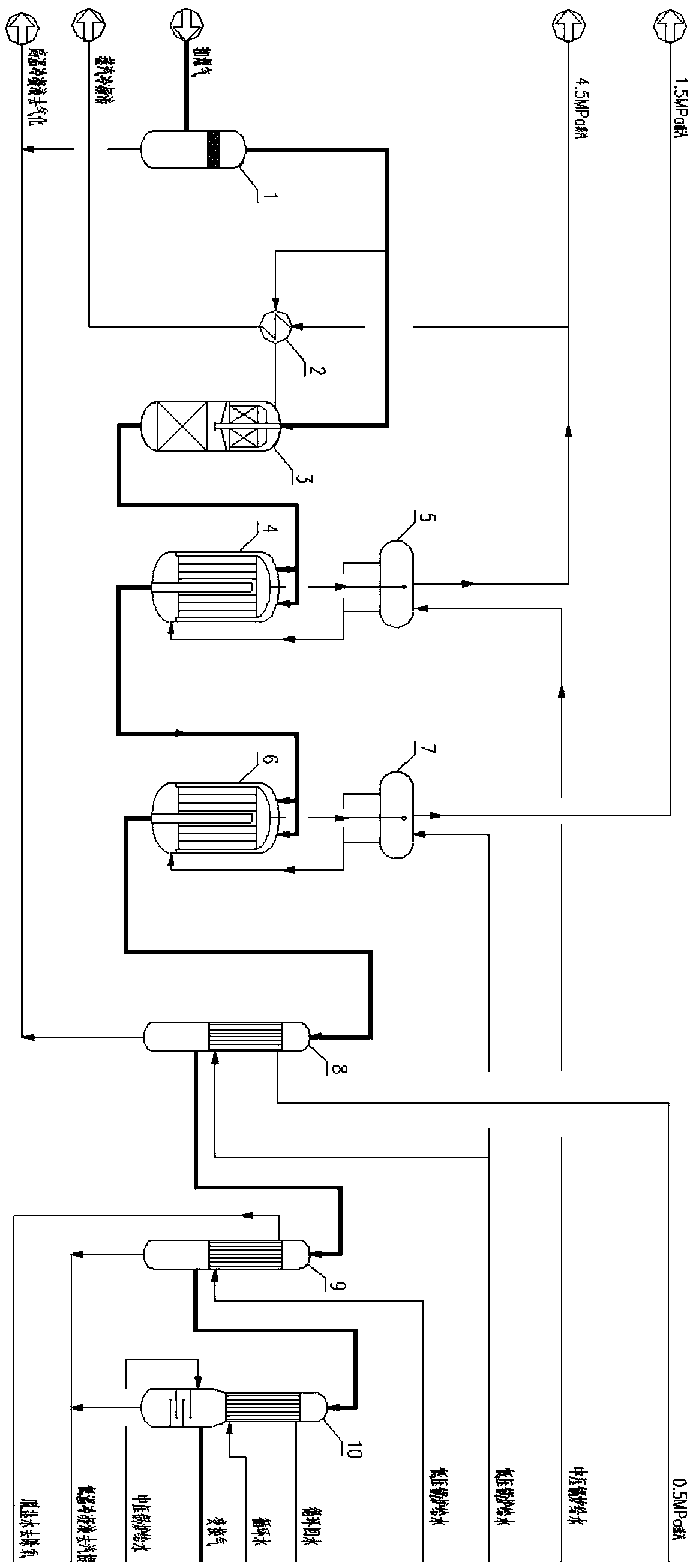
[0043] Such as image 3 As shown, the crude gas from the coal-water slurry gasification device (pressure is 6.0MPaG, temperature 232 ℃) is divided into two shares after separating the liquid water by the raw material gas separator 1, and one of them is about 12% of the crude gas. The heater 2 is heated to 260°C and enters the upper section of the self-heating purification furnace 3. After the reaction, it is mixed with another stream of about 88% crude gas through the central tube, and the temperature is about 265°C, and then the temperature is about 265°C, and the dust and poisons are removed in the lower section of the self-heating purification furnace 3. Then enter the first-stage temperature-controlled shift furnace 4 to carry out the shift reaction. The raw gas entering the temperature-controlled shift furnace, under the action of the inter-tube shift catalyst, CO and H 2 O occurs a shift reaction, and the shift reaction releases a large amount of reaction heat. After he...


PUM


Abstract

The invention relates to a CO-containing raw gas conversion and heat recovery method. The method comprises the following steps: separating condensate from CO-containing raw material gas, dividing theraw material gas into two streams, carrying out a shift reaction on one stream, mixing the shift reaction product with the other stream of raw material gas, and carrying out a shift reaction. Comparedwith the prior art, the problem that the requirement for adjusting the temperature of the shift converter cannot be met by using heat exchange is avoided, the inlet temperature of the shift converteris freely adjusted, and the requirement for later temperature rise of a catalyst can be satisfied well. The method has the advantages of being low in system temperature, high in safety, sufficient inheat recovery, few in equipment, short in flow, small in system resistance, small in occupied area, low in manufacturing cost and the like, and is suitable for wide popularization.

Description

technical field [0001] The invention relates to a CO shift process, in particular to a CO-containing feed gas shift and heat recovery method. Background technique [0002] CO conversion (CO+H 2 O→H 2 +CO 2 ) means that the raw material gas passes through the catalyst in the reactor at a certain temperature and pressure to make the CO and H in it 2 O reacts to form H 2 and CO 2 , so as to achieve the purpose of adjusting the ratio of carbon monoxide and hydrogen. The carbon monoxide conversion process is an indispensable and important process in modern coal chemical industry. [0003] With the rapid development of my country's coal chemical industry, entrained bed gasification technology represented by pressurized gasification of coal water slurry and dry pulverized coal has been applied more and more. The crude gas sent to the conversion by entrained gasification has the characteristics of high CO content, high water-gas ratio, high dew point temperature and high ammon...

Claims


Application Information

Patent Timeline
IPC IPC(8): C01B3/16F22B1/00
CPCC01B3/16F22B1/00C01B2203/1258C01B2203/0495C01B2203/0465Y02P20/10
Inventor 张雄斌
Owner HAISO TECH
Why Eureka
Try Eureka