Sintering device, sintering cooler and its lamination sealing device

A sintered cooling machine and sealing device technology, which is applied in the direction of engine sealing, mechanical equipment, engine components, etc., can solve the problems of adverse effects of waste heat recovery, air volume loss, thermal pollution and dust, etc., to improve the efficiency of waste heat recovery and reduce equipment Air leakage, improve the effect of the environment

Inactive Publication Date: 2009-02-18
锐安得力(北京)安全科技有限公司
View PDF0 Cites 7 Cited by
  • Summary
  • Abstract
  • Description
  • Claims
  • Application Information

AI Technical Summary

Problems solved by technology

Because the pressure inside the bellows is greater than the external pressure, the air leaked from B is normal temperature; the air leaked from A is medium temperature (about 350°C), and the air leaked from A will also bring out a large amount of dust, which not only causes thermal pollution Dust pollution will be caused; cross air (internal leakage) between the fume hoods will be formed at C. Because the temperature of the hot flue gas in the 1# fume hood 21 and the 2# fume hood 22 is different, generally the difference is about 150°C, and the 1# fume hood The hot flue gas in 21 is generally connected to the waste heat boiler for waste heat recovery, and the waste heat boiler produces steam for production or domestic use. If the flue gas in 1# fume hood 21 is strung into 2# fume hood 22, the waste heat utilization will be effective The air volume is reduced. If the flue gas in the hood 22 of 2# enters the hood 21 of 1#, the temperature of the flue gas in the hood 21 of 1# will be lowered. thus adversely affecting waste heat recovery

Method used


Image

  • Sintering device, sintering cooler and its lamination sealing device
  • Sintering device, sintering cooler and its lamination sealing device
  • Sintering device, sintering cooler and its lamination sealing device

Examples


Embodiment Construction

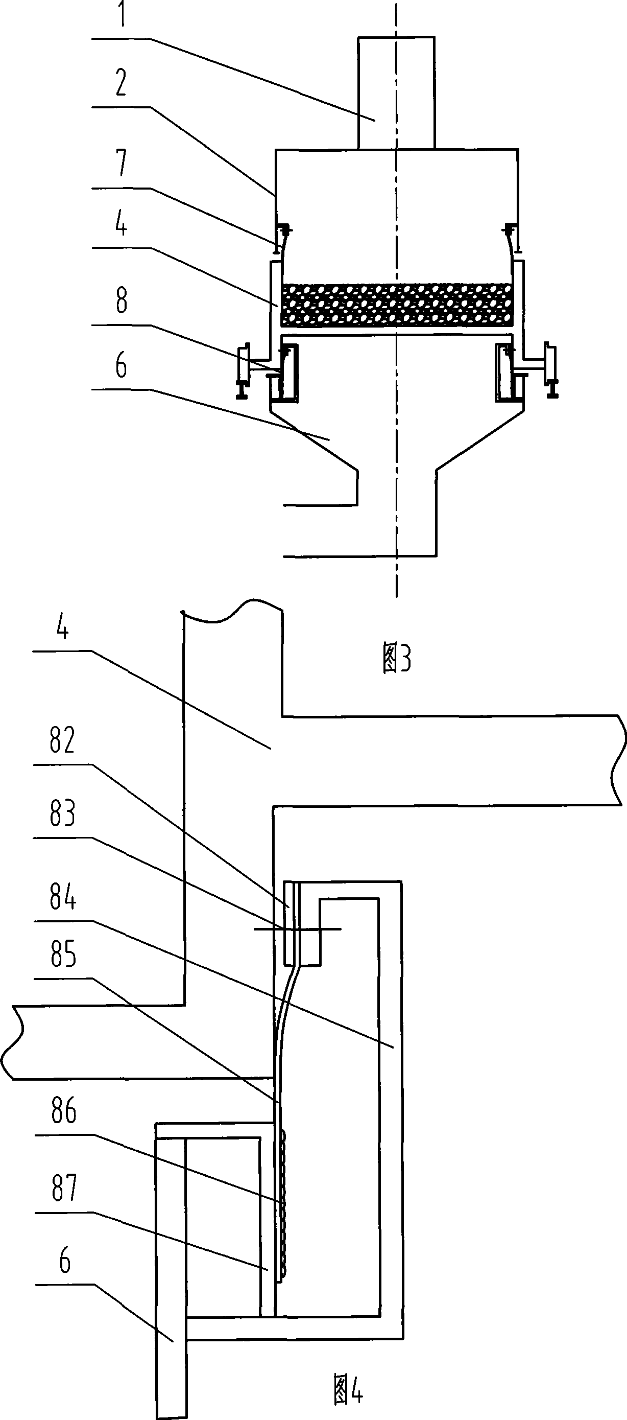
[0056] Firstly, the four sealing methods of the present invention will be described with reference to the accompanying drawings, namely 1. flexible sealing, 2. laminated sealing, 3. hanging sealing, and 4. mosaic sealing. Next, embodiments of the present invention will be described.

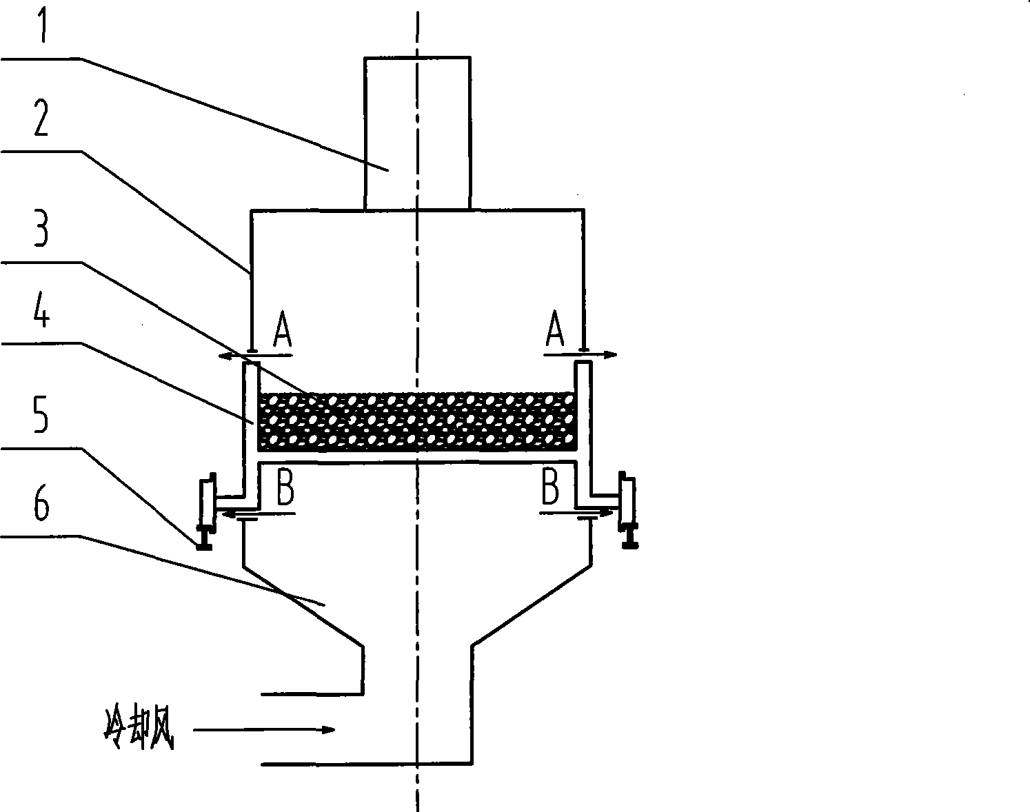
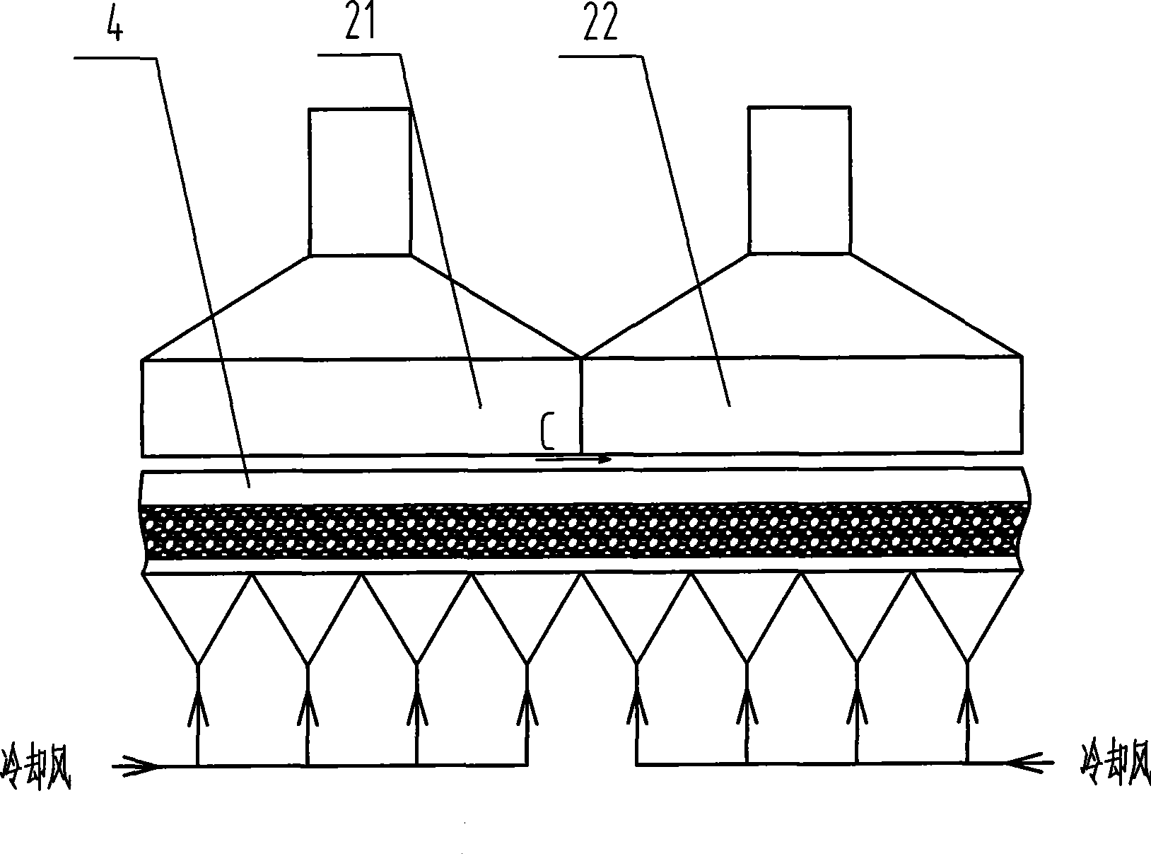
[0057] Also, in the context of the present invention, the trolley 4 is divided into two parts, namely an upper trolley part and a lower trolley part. The upper part of the trolley generally refers to the part of the trolley above the bearing plate carrying the sintered ore 3, and the lower part of the trolley refers to the part of the trolley under the bearing plate.

[0058] It should be noted that although the sintering cooling machine is used as an example for description below, the present invention is also applicable to general sintering machines. Specifically, because the existing sintering machine usually does not have a fume hood 2, in general, the sintering machine of the present invent...


PUM


Abstract

The invention discloses a sintering machine or a sintering cooler and a lamination seal equipment thereof, which can reduce the power consumption of blowers, decrease the air leakage of the equipment, increase the waste heat recovery efficiency and improve the environment. The sintering cooler comprises a sinter-loading trolley, an overhead hood above the trolley, a bellows below the trolley, an upper lamination seal device between the hood and the upper part of the trolley, as well as a lower lamination seal device or a lower flexible seal device arranged between the lower part of the trolley and the bellows; wherein, the slideway of the bellows is glidingly contacted with a flexible slide plate of the trolley; the upper lamination seal device is used to seal the gap between the hood and the upper part of the trolley; and the lower lamination seal device or the lower flexible seal device is used to seal the gap between the lower part of the trolley and the bellows.

Description

technical field [0001] The invention relates to a sealing device for metallurgical equipment, in particular to a sintering machine, a sintering cooling machine and the lamination sealing device thereof. Background technique [0002] In metallurgical production, the sintering machine is used to sinter ore powder into sintered ore, and the sintered ore is cooled to below 150°C by the sintering cooler, and then sent to the smelting process. Sinter production is an important process in steel production, and it is also a process that consumes a lot of energy. [0003] Various sintering machines widely used now include belt-type sintering machines, machine-cooled sintering machines, ring-type sintering machines and plane stepping sintering machines, etc. All kinds of sintering machines have serious air leakage problems. The rate is generally 40%-50%, and some are as high as 70%. Air leakage greatly reduces the effective air volume, resulting in increased energy consumption and r...

Claims


Application Information

Patent Timeline
Patent Type & Authority Applications(China)
IPC IPC(8): F27B21/08F27D17/00F27D15/02F16J15/02
CPCY02P80/15
Inventor 刘庸李琳
Owner 锐安得力(北京)安全科技有限公司
Why Eureka
Try Eureka