
Outer-side-rotation rotor for dynamo-electric machines

A rotating electrical machine, externally rotating technology, applied in synchronous motors with stationary armatures and rotating magnets, manufacturing stator/rotor bodies, electromechanical devices, etc. Inability to carry out sufficient reinforcement and fixation, etc., to achieve the effect of stabilizing dimensional characteristics and electrical characteristics

Active Publication Date: 2009-08-26
TOSHIBA LIFESTYLE PROD & SERVICES CORP
View PDF5 Cites 0 Cited by
  • Summary
  • Abstract
  • Description
  • Claims
  • Application Information

AI Technical Summary

Problems solved by technology

However, there are few types of thermosetting resins, and there are also few types of additives used to improve physical properties, etc., and the setting range of molding conditions is narrow.
Therefore, it is not easy to change the physical properties of the resin (such as strength and fluidity)
Therefore, for example, even if a thermosetting resin is used for a rotor core with a large number of laminations and a low strength, sufficient reinforcement and fixation may not be possible.
As a result, it may adversely affect the characteristics of the rotor and rotating electrical machine

Method used


Image

  • Outer-side-rotation rotor for dynamo-electric machines
  • Outer-side-rotation rotor for dynamo-electric machines
  • Outer-side-rotation rotor for dynamo-electric machines

Examples


Embodiment Construction

[0020] Next, an embodiment in which the present invention is applied to an externally rotating permanent magnet motor (rotating electric machine) will be described with reference to the drawings.

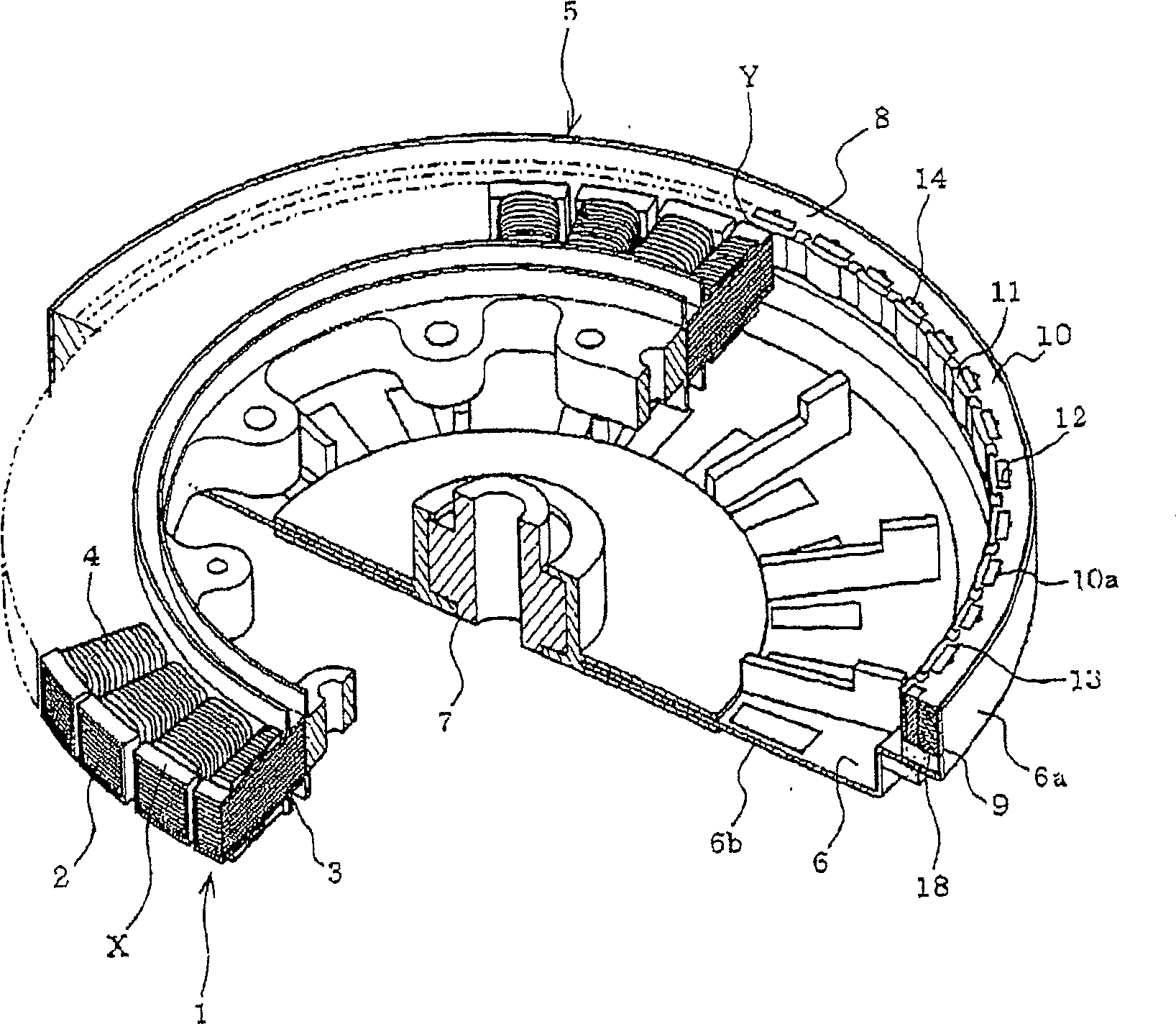
[0021] figure 2 It is a perspective view showing a part of the motor cut away. exist figure 2 Among them, the stator 1 includes: a stator core 3 having a plurality of teeth 2 radially; a stator resin X provided to cover the stator core 3 ; and a stator winding 4 wound around each tooth 2 .

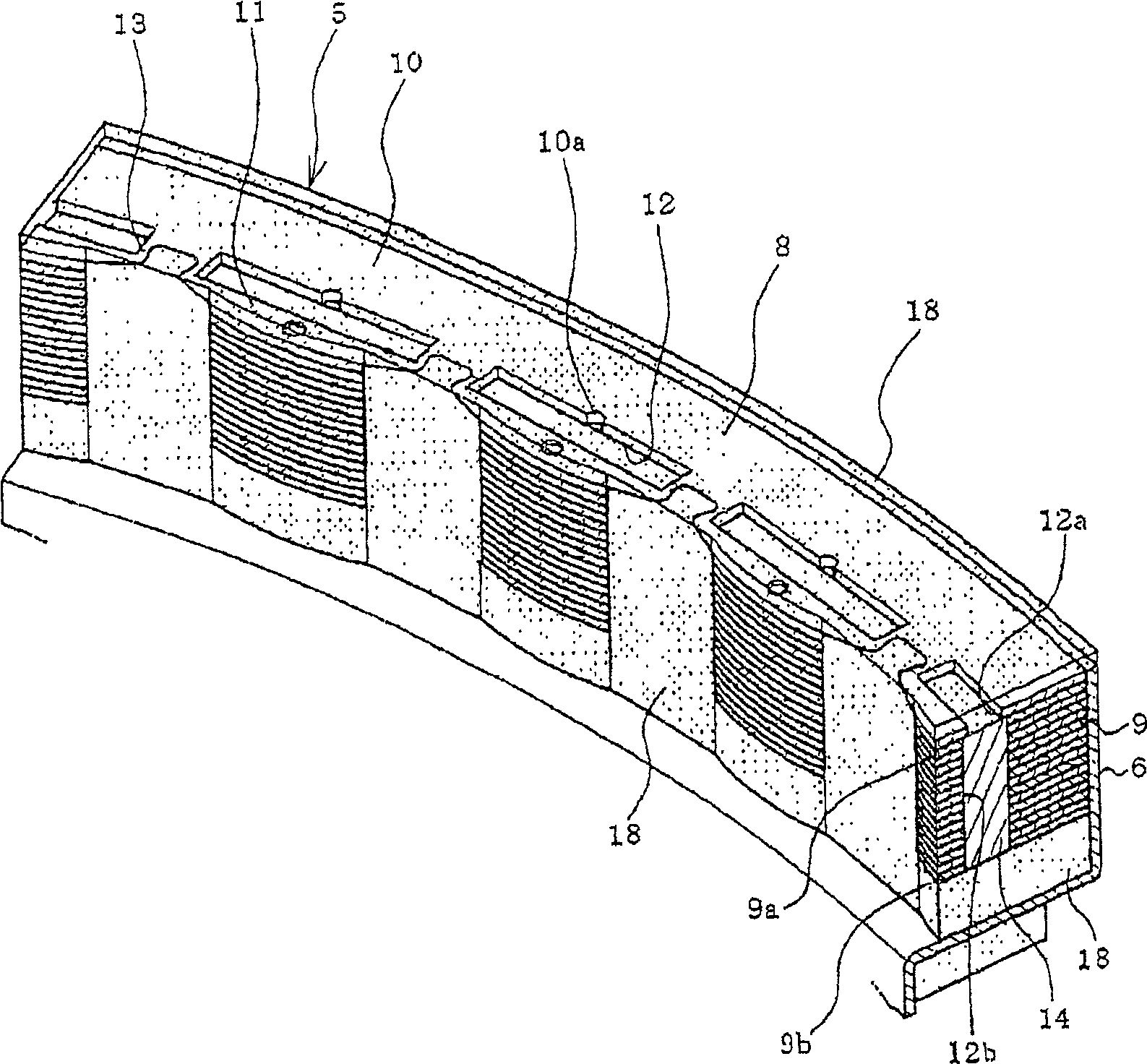
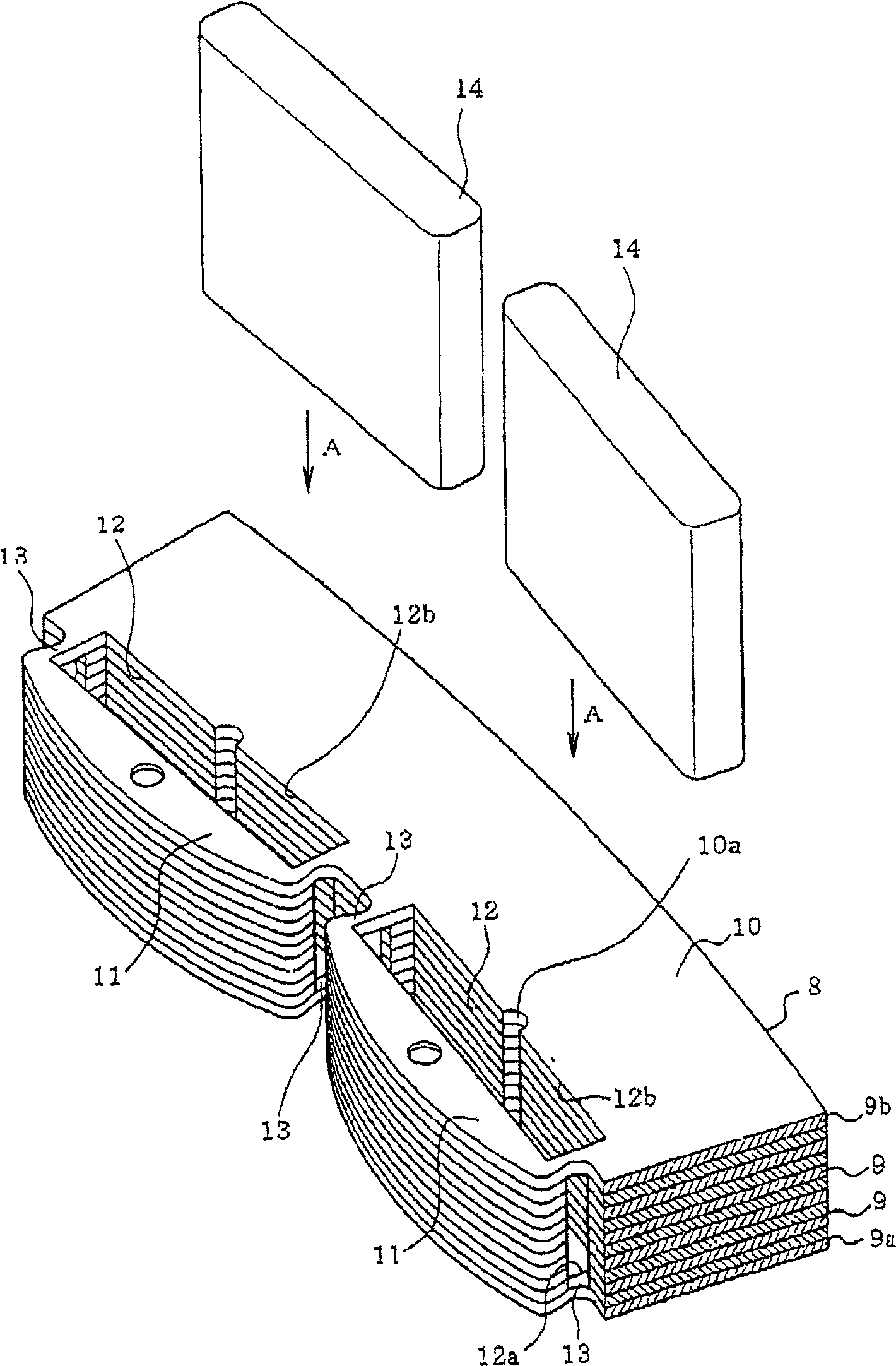
[0022] The outwardly rotating rotor 5 has a frame 6 made of a magnetic body in the shape of a circular container with an open top. A shaft support body 7 is fixed to the central portion of the frame 6 . An annular wall 6a is provided on the opening side of the outer peripheral portion of the frame 6, and the rotor core 8 is arranged along the inner periphery of the annular wall 6a. The rotor core 8 is formed by punching out an electromagnetic steel sheet to form a punched plate 9 and stack...


PUM


Abstract

The externally rotating rotor of a rotating electrical machine of the present invention comprises: a rotor core (8) having a magnet insertion hole (12); a permanent magnet (14) inserted into the magnet insertion hole (12); and a resin molding material (18) The permanent magnet (14) is integrated with the rotor core (8) and the rotor core (8) itself, and the resin is thermoplastic resin.

Description

technical field [0001] The present invention relates to an externally rotating rotor of a rotating electrical machine in which permanent magnets are inserted into magnet insertion holes formed in a rotor core. Background technique [0002] A rotating electrical machine such as an outer rotor type permanent magnet motor (permanent magnet motor) includes a substantially cylindrical stator in which coils are housed in slots, and a rotor located around the stator opposite to each other across a gap. On the inner peripheral surface of the rotor, a plurality of permanent magnets for magnetic poles formed in an arc shape along the inner peripheral surface are fixed, for example, by bonding. Thus, magnetic poles are formed on the rotor. For the permanent magnets for magnetic poles, ferrite magnets having a high degree of freedom in forming (shape) and high strength are widely used. [0003] However, high efficiency of equipment is required in various fields represented by the hom...

Claims


Application Information

Patent Timeline
Patent Type & Authority Patents(China)
IPC IPC(8): H02K1/27H02K1/22H02K15/03H02K21/22
CPCH02K1/2786H02K1/2791H02K1/27H02K21/22
Inventor 志贺刚五藤嘉康
Owner TOSHIBA LIFESTYLE PROD & SERVICES CORP
Learn More