Air condenser

一种气冷式、冷凝器的技术,应用在蒸汽/蒸气冷凝器、蒸发器/冷凝器、制冷机等方向,能够解决大安装高度、大空间等问题,达到强制冷能力、轻支撑结构、大可利用区域的效果

Active Publication Date: 2009-09-09
SPG AIR COOLING BELGIUM CO
View PDF8 Cites 2 Cited by
  • Summary
  • Abstract
  • Description
  • Claims
  • Application Information

AI Technical Summary

Problems solved by technology

[0003] However, the air-cooled condenser with the above-mentioned triangular design and strong cooling capacity requires a lot of space and also requires a large installation height, so expensive substructures are required
Also, the difficulty with air-cooled condensers is to distribute the same amount of steam to each tube bundle

Method used


Image

  • Air condenser
  • Air condenser
  • Air condenser

Examples


Embodiment Construction

[0017] Hereinafter, the present invention will be described in more detail with reference to the illustrated embodiments.

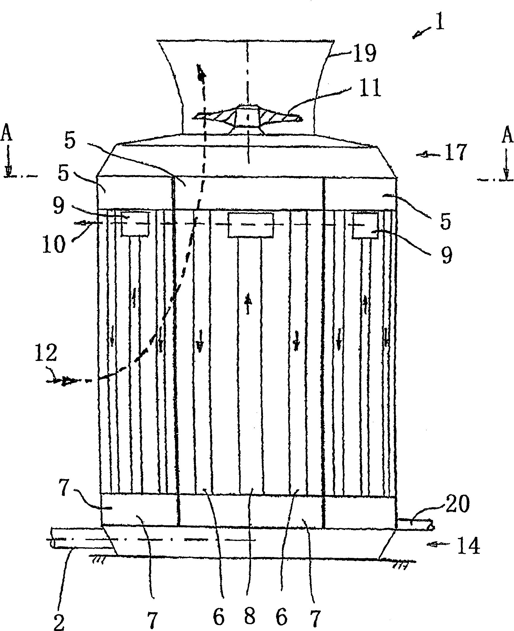
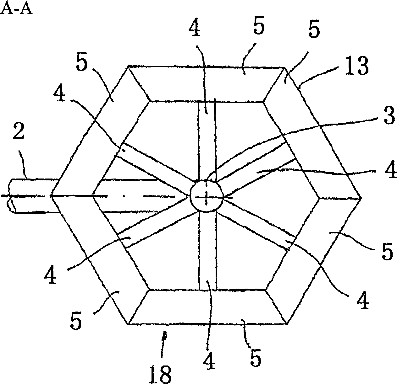
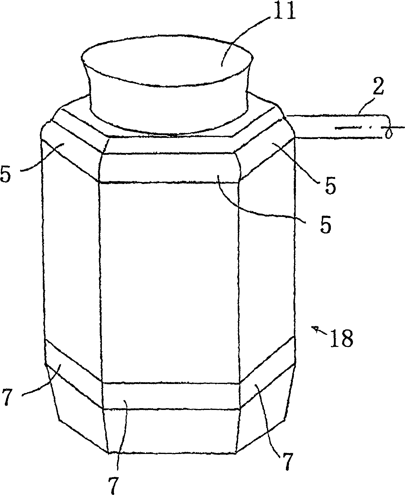
[0018] Such as figure 1 and figure 2 As shown, steam is supplied to the air-cooled condenser 1 of the present invention by using the supply line 2 . Thus, the steam flows upwards through one or more riser throats 3 and is distributed through distribution lines 4 to respective distribution chambers 5 . It should be pointed out that in figure 2 Only one ascending throat is shown in . The distribution line is figure 2 is only shown schematically; it can also be expanded or divided into several lines leading to the distribution chamber 5 .

[0019] The distribution chamber 5 is arranged in the upper region of the air-cooled condenser. Below the distribution chamber 5 there is provided a bundle of conduits, which is designated 6 in the figure. Corresponding to the diameter of the fan, one, two or more duct bundles can be arranged on each side wall 18...


PUM


Abstract

An air-cooled condenser (1) for condensing steam by air, said air-cooled condenser comprising: a steam supply line (2); at least one upwardly directed conduit bundle (6) for the Steam is supplied to the bundle of tubes; a condensate drain for discharge of condensed steam; a fan (11) for conveying air to the bundle of tubes. The duct bundle (6) is arranged below the fan (11), in the side wall (18) of the air-cooled condenser (1); and a plurality of duct bundles (6) are arranged in the following manner: they are polygonal along the The plumb line extends to form a mantle (13), wherein said mantle is closely packed so that it forms a fence on all sides.

Description

technical field [0001] The invention relates to an air-cooled condenser for condensing steam by air. Background technique [0002] As is known, an air-cooled condenser comprises an arrangement of tubes arranged parallel to one another, also called a tube bundle, to which the steam to be condensed is supplied. In this way, every two rows of conduit bundles are usually arranged in the shape of apexes inclined to each other at an acute angle. Viewed from the side, they form a triangular profile with a fan at their base for supplying air to the duct bundle. In such a way that heat exchange occurs, the fan delivers air cooler than the steam to the bundle of tubes, whereby the steam can condense on the inner edge of each tube in the bundle of tubes. [0003] However, the air-cooled condenser with the above-mentioned triangular design and powerful cooling capacity requires a large space and also requires a large installation height, thus requiring an expensive substructure. Also...

Claims


Application Information

Patent Timeline
Patent Type & Authority Patents(China)
IPC IPC(8): F28B1/06
CPCF28B1/06F28B9/02F25B39/04F28D1/04
Inventor 米歇尔·沃琪菲利普·纳格尔
Owner SPG AIR COOLING BELGIUM CO
Why Eureka
Try Eureka