Moving crane

A technology for moving cranes and hoists, applied in the direction of cranes, trolley cranes, load hanging elements, etc., can solve problems such as adverse effects of weather and lighting conditions, inaccurate steering movements and activities, and cumbersome spare parts. , to achieve stable travel, improved weight distribution, and low carbon emissions

Inactive Publication Date: 2016-12-14
KONECRANES GLOBAL
View PDF10 Cites 4 Cited by
  • Summary
  • Abstract
  • Description
  • Claims
  • Application Information

AI Technical Summary

Problems solved by technology

The crane operator views the load member from above at an angle from the cab, and any steering movements and activities on the loading area, especially those close to ground level, may be imprecise
They are further adversely affected by adverse weather and lighting conditions
[0005] The prior art solutions also require that demanding repair and maintenance procedures be taken into account in the elevated position, wherein also the necessary, possibly heavy and bulky spare parts associated with the repair operations have to be taken into account

Method used


Image

  • Moving crane

Examples


Embodiment Construction

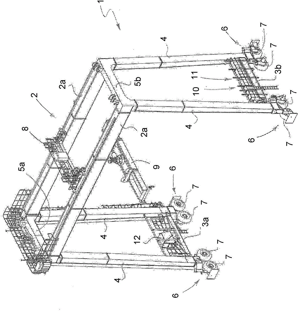
[0019] With reference to the drawings, a mobile crane according to the invention has a frame 1 having in its upper part a main support structure 2 and in its lower part and on opposite sides of the lower part of the frame 1 transverse The lower beam structures 3a and 3b of the main support structure 2. The main support structure 2 is connected by upstanding feet 4 to the lower beam structures 3a and 3b. The main support structure 2 here comprises two main supports 2a spaced apart from each other, running in parallel and connected to each other by means of upper beam structures 5a and 5b.

[0020] The ends of the lower beam structures 3 a and 3 b have bogie structures 6 each comprising two consecutive wheels 7 . The total number of bogie structures 6 is thus four, one in each lower corner of the crane. In this example the wheels are rubber wheels and generally one of the wheels 7 of each bogie structure 6 is a driving wheel and the other is a driven wheel. In relation to rub...


PUM


Abstract

A moving crane comprising a frame (1) which, in its upper part, is provided with a main support structure (2) and which, in its lower part and on opposite sides of the lower part of the frame, is provided with lower beam structures (3a, 3b) transverse to the main support structure; at least one wheel or wheel arrangement (6, 7) at both ends of the lower beam structures (3a, 3b), i.e. in each lower corner of the crane; a trolley (8) arranged to move along the main support structure (2) and provided with a hoisting member (9); a hoisting mechanism (10) for driving the hoisting member (9) of the trolley (8), and a cab (12) for the crane operator, whereby the cab (12) is placed in connection with one lower beam structure (3a) and the hoisting mechanism (10) in connection with the other lower beam structure (3b).

Description

technical field [0001] The invention relates to a mobile crane comprising a frame having in its upper part a main support structure and in its lower part on opposite sides of the lower part of the frame having a lower beam structure transverse to the main support structure; at least one wheel or wheel arrangement at both ends of the lower beam structure, ie in each lower corner of the crane; a crane arranged along the main support structure and the crane has a lifting member; a lifting mechanism for driving the lifting member of the crane; and a cab for an operator of the crane. Background technique [0002] Such gantry cranes for storage areas in container terminals are designed for arranging and handling containers in container storage yards. They move along paths parallel to the row of containers on either rails or rubber wheels. [0003] Typically, the crane's cab and hoisting mechanism are provided in a crane moving on top of the crane's main support structure, which ...

Claims


Application Information

Patent Timeline
Patent Type & Authority Applications(China)
IPC IPC(8): B66C19/00B66C13/54
CPCB66C13/54B66C19/00B66C19/007B66C13/16B66C13/18
Inventor E·奥加帕罗J·桑塔拉H·奥亚
Owner KONECRANES GLOBAL
Why Eureka
Try Eureka