Supercharge Your Innovation With Domain-Expert AI Agents!

Heat exchanger

A technology for heat exchangers and plate heat exchangers, which is applied in the directions of heat exchange equipment, heat exchanger types, heat exchanger shells, etc. Reduce and simplify the effect of piping layout

Inactive Publication Date: 2009-09-16
LINDE AG
View PDF5 Cites 0 Cited by
  • Summary
  • Abstract
  • Description
  • Claims
  • Application Information

AI Technical Summary

Problems solved by technology

In this case, the pipe arrangement of the plate heat exchanger is very complicated, which increases the manufacturing cost

Method used


Image

  • Heat exchanger
  • Heat exchanger
  • Heat exchanger

Examples


Embodiment Construction

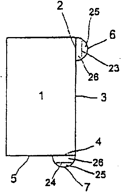
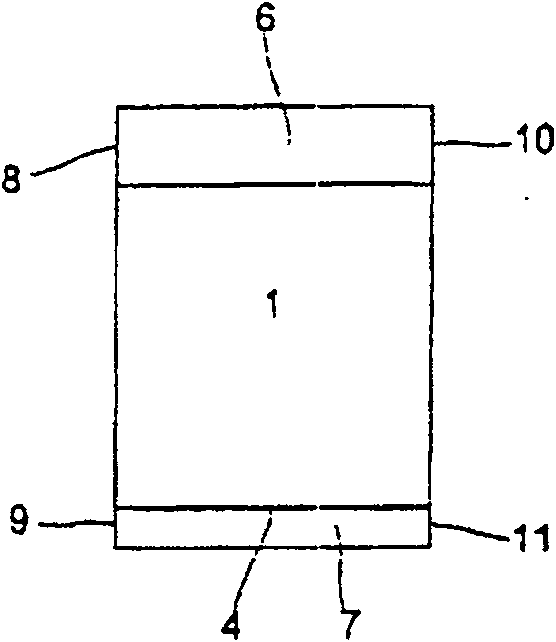
[0026] figure 1 with figure 2 A plate heat exchanger available from the prior art is shown. The plate heat exchanger comprises a heat exchanger body 1 with a plurality of heat exchange channels, which are not shown in the figure for the sake of clarity. The inlet and outlet holes of a group of heat exchange channels are respectively located at area 2 on the side wall 3 of the heat exchanger body 1 and at area 4 on the bottom surface 5 of the heat exchanger body 1 . Semi-cylindrical headers 6 and 7 are welded to areas 2 and 4 with inlet and outlet holes.

[0027] The headers 6 and 7 are designed as semi-cylindrical housings with bases 8 , 9 , 10 and 11 . Guide plates 23 and 24 are arranged in the headers 6 and 7 , which further divide the space in the headers 6 and 7 into a flow area 25 and a distribution area 26 . The guide plates 23 and 24 have a plurality of holes so that an exchange of gas and liquid between the flow zone 25 and the distribution zone 26 is possible.

...


PUM


Abstract

The invention discloses a plate heat exchanger, which includes a heat exchanger body with a plurality of heat exchange channels. Mounted to the heat exchanger body is a header extending across at least a portion of one side of the heat exchanger body and providing fluid communication between portions of the heat exchange channels. And the header also has a fluid communication line disposed substantially perpendicular to the side of the header extending through the heat exchanger body.

Description

technical field [0001] The invention relates to a plate heat exchanger comprising a heat exchanger body with a plurality of heat exchange channels, on which a header is mounted, the header extending through the heat exchanger body and at least a portion of one side of the heat exchange channel, and fluid communication between portions of the heat exchange channel, and the header also has a fluid communication member disposed substantially perpendicular to the heat exchanger body The side through which the header extends. Background technique [0002] The heat exchanger body of a plate heat exchanger comprises multiple layers of heat exchange channels which are delimited to each other by partitions in each layer. The closing strip and the cover plate form the outer frame of the heat exchanger body. It is also possible to arrange more spacers within one layer, thereby separating the heat exchange channels for the different streams from each other. [0003] The heat exchange...

Claims


Application Information

Patent Timeline
Patent Type & Authority Patents(China)
IPC IPC(8): F28F9/04F28F9/02F28D9/00F28F9/26
CPCF28D9/0043F28F9/0246F28D9/0037F28F9/26
Inventor 斯特凡·默勒阿尔弗雷德·万纳加布里埃莱·恩格尔托马斯·黑希特沃尔夫冈·聚斯曼赫伯特·艾格纳
Owner LINDE AG
Features
  • R&D
  • Intellectual Property
  • Life Sciences
  • Materials
  • Tech Scout
  • Unparalleled Data Quality
  • Higher Quality Content
  • 60% Fewer Hallucinations
Learn More