Flow controller
A technology of flow controller and deflector, which is applied in the direction of flow control without auxiliary power, sanitary equipment for toilets, water supply devices, etc., to achieve the effect of stabilizing the liquid output
- Summary
- Abstract
- Description
- Claims
- Application Information
AI Technical Summary
Problems solved by technology
Method used
Image

Examples
Embodiment 1
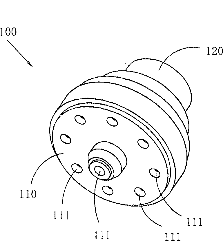
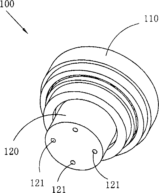
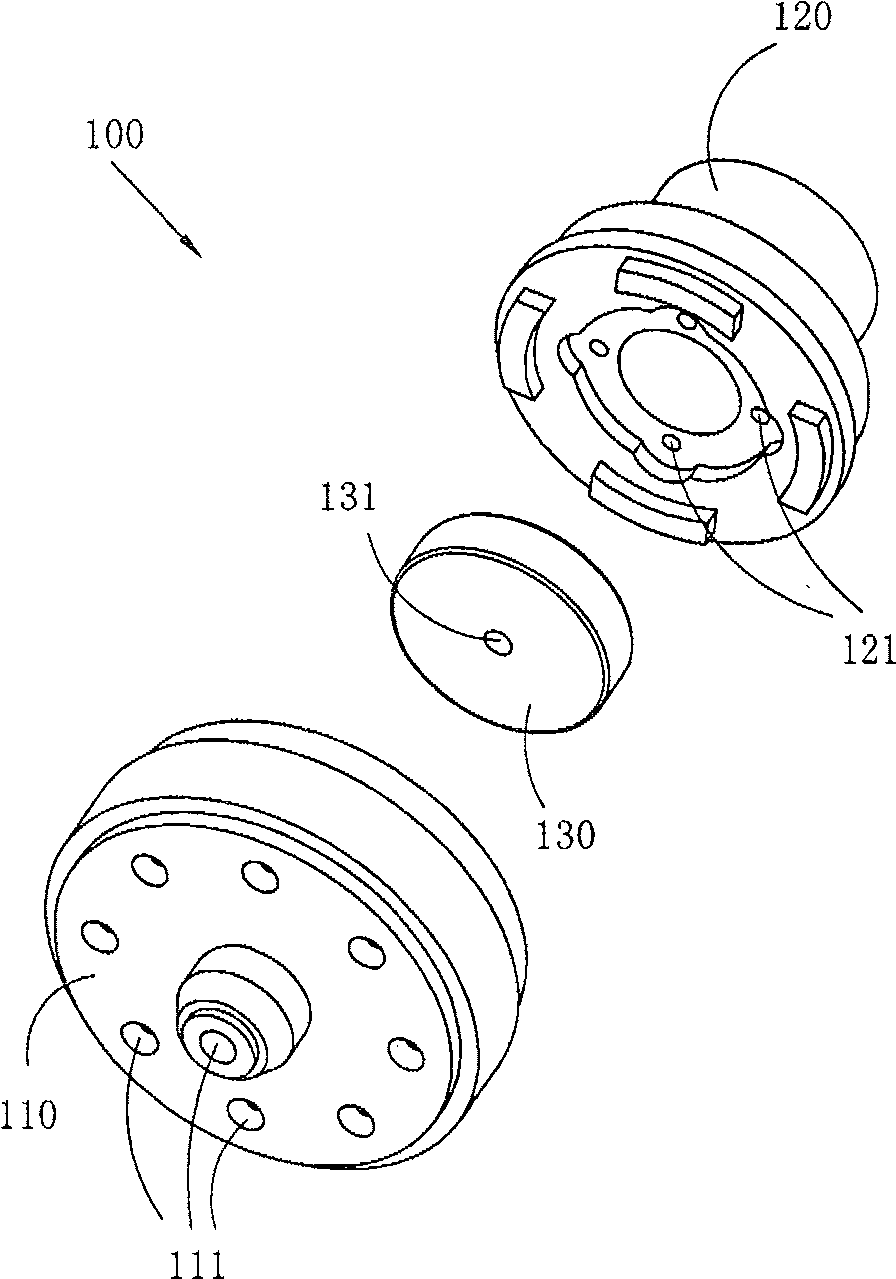
[0056] Figure 5 to Figure 13 A first embodiment of the flow controller of the present invention is shown, wherein Figure 5 It is a three-dimensional schematic diagram of the first structure of the flow controller of the present invention. Figure 6 yes Figure 5 The schematic diagram of the three-dimensional structure of the flow controller shown when viewed from another angle. Figure 7 yes Figure 5 Schematic diagram of the half-section structure of the flow controller shown. Figure 8 yes Figure 5 The schematic diagram of the three-dimensional structure of the deflector in the flow controller shown. Figure 9 yes Figure 8 The three-dimensional structure schematic diagram of the deflector shown when viewed from another angle. Figure 10 yes Figure 8 Schematic diagram of the half-section structure of the deflector shown. Figure 11 yes Figure 5 The schematic diagram of the three-dimensional structure of the restrictor in the flow controller shown. Figure 12 ...
Embodiment 2
[0061] Figure 14 to Figure 18 A second embodiment of the invention is shown, in which Figure 14 It is a half-section schematic diagram of the second structure of the flow controller of the present invention. Figure 15 yes Figure 14 The schematic diagram of the three-dimensional structure of the deflector in the flow controller shown. Figure 16 yes Figure 15 Schematic diagram of the half-section structure of the deflector. Figure 17 yes Figure 14 The schematic diagram of the three-dimensional structure of the restrictor in the flow controller shown. Figure 18 yes Figure 17 Schematic diagram of the half-section structure of the current limiter shown.
[0062] This embodiment is basically the same as Embodiment 1, see Figure 14 to Figure 18 , the difference is that: the strut 3 for supporting the flow restrictor 2 is arranged at the liquid inlet end 112 of the deflector main body 11, and the flow restrictor 2 is no longer provided with a strut 3 .
Embodiment 3
[0064] See Figure 19 to Figure 21 ,in Figure 19 It is a schematic diagram of a half-section structure of the third structure of the present invention, Figure 20 yes Figure 19 The schematic diagram of the three-dimensional structure of the flow restrictor in the shown flow controller, Figure 21 yes Figure 20 The schematic diagram of the three-dimensional structure of the current limiter when viewed from another angle, Figure 22 yes Figure 21 Partial cross-sectional view of the flow restrictor shown.
[0065] This embodiment is basically the same as Embodiment 1, except that the shape of the strut 3 arranged on the side end of the flow restrictor that is closer to the main body 11 of the flow deflector is different from that of Embodiment 1. Embodiment 1 The basic shape of the pillars 3 is cylindrical, and the pillars 3 in this embodiment are three fan-shaped pillars connected together, and a groove as the liquid inlet channel 4 is formed between two adjacent pilla...
PUM
 Abstract
Description
Claims
Application Information