
Magnetically controlled locking device

A locking device, magnetic control technology, applied in the direction of building locks, cylinder locks, locks with turning keys, etc., to achieve the effect of optimizing accuracy

Inactive Publication Date: 2009-10-14
CONCEPTS & INNOVATIONS & SECURITE MAGNETIQUE
View PDF6 Cites 0 Cited by
  • Summary
  • Abstract
  • Description
  • Claims
  • Application Information

AI Technical Summary

Problems solved by technology

[0006] The main problem with such devices is that the limited number of combinations makes it possible to manufacture said devices that may be manipulated by common or partial master keys or that may be of varying configurations

Method used


Image

  • Magnetically controlled locking device
  • Magnetically controlled locking device
  • Magnetically controlled locking device

Examples


Embodiment Construction

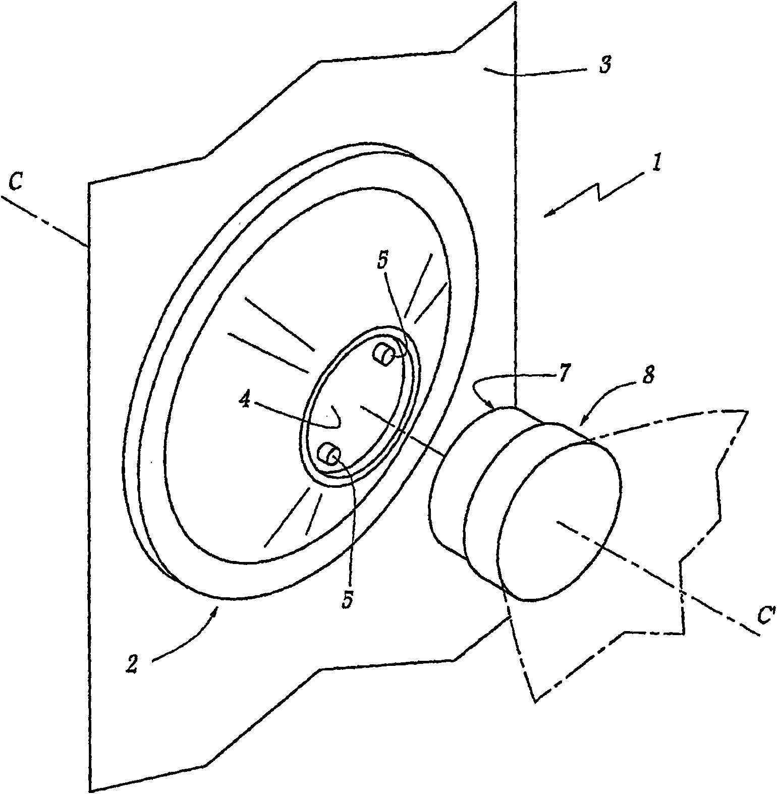
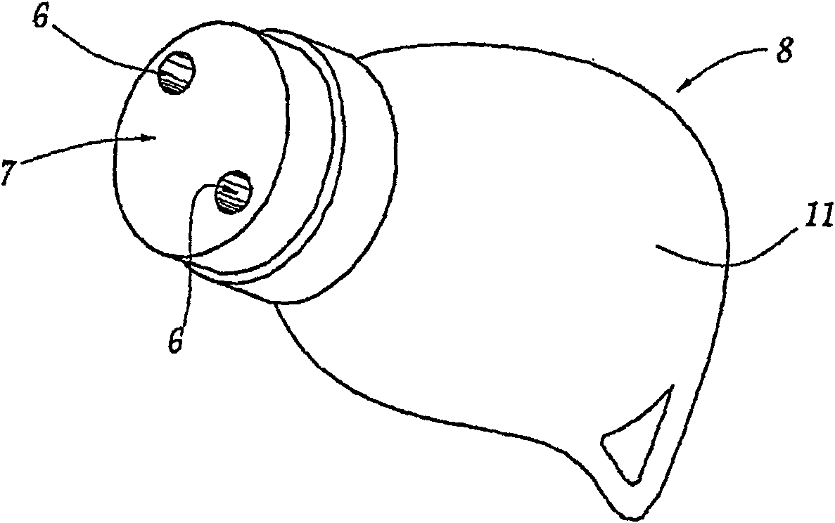
[0034] figure 1 The device 1 shown comprises a front face 2 on a face 3 of the door. The front face is made of metal such as steel and is fixed to the door so that there are no voids or gaps that can be used to "press" the device 1. The front face 2 is dome-shaped, which has a circular bottom with the top face 4 truncated. The top surface 4 is composed of a flat, smooth, and circular plate. Two diametrically opposed studs 5 are provided on its periphery. These studs 5 have two small-sized cylindrical shapes, the longitudinal axis of which is located in a direction completely perpendicular to the plane of the surface 3. They have a shape suitable for insertion into the depression 6 which is located on the flat surface 7 of the key 8. The surface 7 is strong and smooth, and its shape and size are complementary to those of the top surface 4. The introduction of the stud 5 into the depression 6 makes it possible to position the key on the plane 4 of the device.

[0035] The contact ...


PUM


Abstract

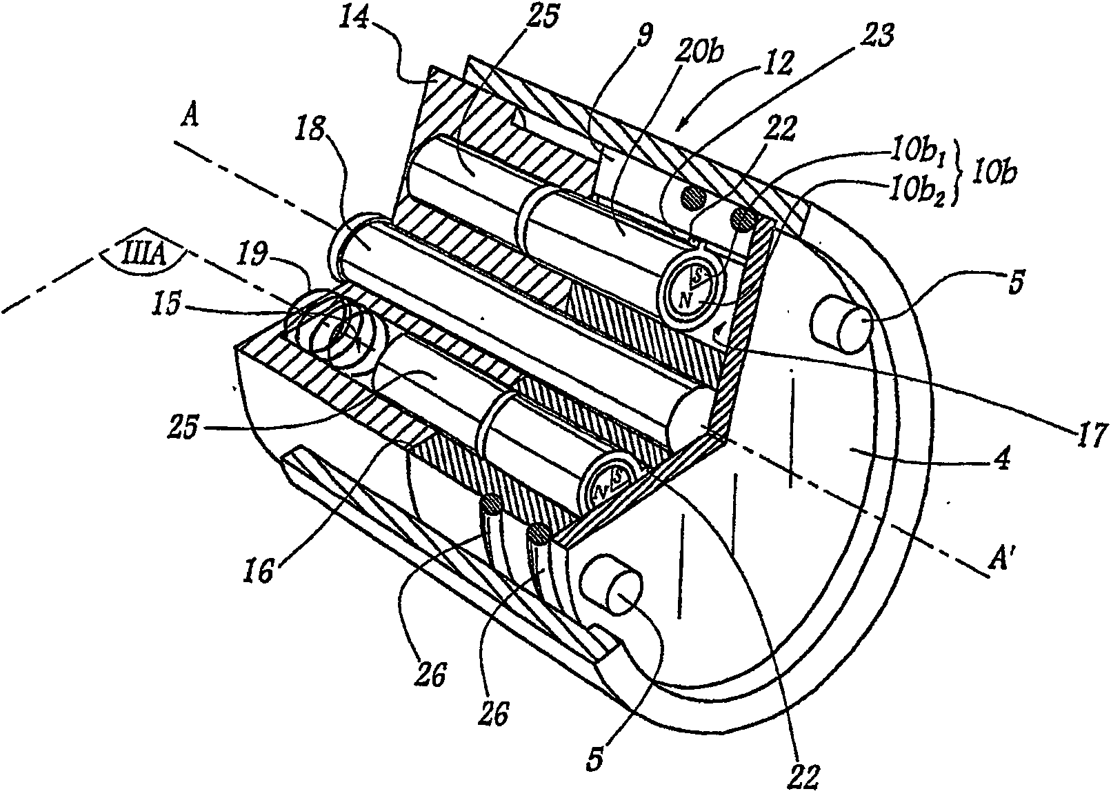
The device comprises a stator ( 14 ) and a rotor ( 9 ) rotated by a key ( 8 ). The latter comprises several bushings ( 10 c) which clasp the magnets ( 10 c) and attract or repel magnets ( 10 b1 , 10 b2) having a complementary or identical polarity and which are disposed inside the bushings ( 10 b) such that they move inside the housings ( 17 ) of the rotor ( 9 ). In order to maintain the angular position thereof and to facilitate translatory guidance, the bushings ( 20 b) comprise a rotational locking element ( 22 ) which engages into a groove ( 23 ) of the corresponding housing ( 17 ). In order to increase the number of combinations, each bushing ( 10 b) of the rotor ( 9 ) or key ( 8 ) houses two magnets ( 10 1 , 10 b2) having inverted polarity or a magnet provided with at least one bipolar extremity, which are adapted in such a way that they can occupy different angular positions about a longitudinal axis (BB') of the bushing ( 10 b , 10 c). Such a device, by virtue of the precision of the relative movements of the axis and the high number of possible combinations, makes it possible to increase the inviolability of a locking device designed to prevent access to an opening.

Description

Technical field [0001] The invention relates to an improved magnetic control locking device. Background technique [0002] European patent application EP 633375 A discloses a magnetically controlled locking device comprising a key and a cylinder. The cylinder includes a stator and a rotor, and the rotor is arranged to rotate around the longitudinal axis of the cylinder with a key. The cylinder supports a plurality of magnets located in a direction completely parallel to the direction of the rotor rotation axis. These magnets cooperate with other magnets distributed relatively on the key. These magnets are wrapped tightly by bushings made of ferromagnetic metal. The bushing for supporting the magnet located in the cylinder can migrate in a shell of complementary shape. [0003] When the part of the key supporting the magnet exists relative to the magnet of the corresponding part of the rotor, the magnets attract or repel each other according to the polarity and respective position...

Claims


Application Information

Patent Timeline
Patent Type & Authority Patents(China)
IPC IPC(8): E05B47/00E05B27/08
CPCE05B47/0044Y10T70/7057E05B27/08
Inventor 耶苏·洛佩斯
Owner CONCEPTS & INNOVATIONS & SECURITE MAGNETIQUE
Learn More