Supercharge Your Innovation With Domain-Expert AI Agents!

Power management device and method of north bridge

A technology of power management and power state, applied in the direction of data processing power, etc., can solve the problems of inability to manage power state, proper management of power consumption of main memory and chipset, etc.

Active Publication Date: 2009-10-21
VIA TECH INC
View PDF3 Cites 0 Cited by
  • Summary
  • Abstract
  • Description
  • Claims
  • Application Information

AI Technical Summary

Problems solved by technology

However, in traditional computer systems, the power consumption of main memory and chipset is not properly managed according to the power state of the processor, and it is not defined in ACPI
[0016] Typically, the power state machine is built in the south bridge, however, the traditional north bridge between the CPU and the main memory cannot manage its power state

Method used


Image

  • Power management device and method of north bridge
  • Power management device and method of north bridge
  • Power management device and method of north bridge

Examples


Embodiment Construction

[0027] The present invention provides a power state management method for a north bridge.

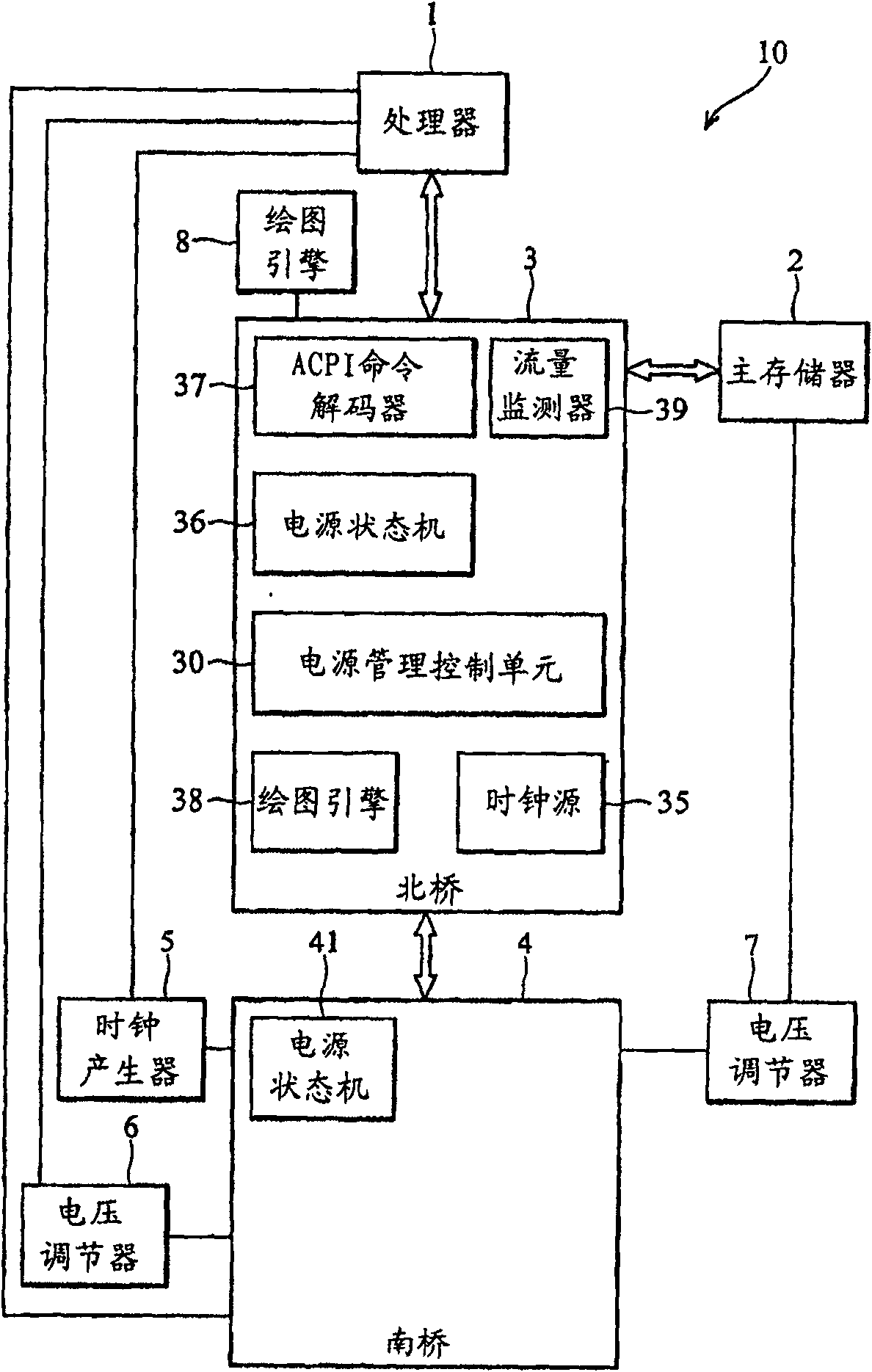
[0028] figure 1 The computer system 10 with the Northbridge power state management function of the present invention is shown.

[0029] The computer system 10 includes a processor 1, a main memory 2, a north bridge (abbreviated as NB) 3 connected between the processor 1 and the main memory 2, and a south bridge (abbreviated as SB) 4 connected to the north bridge 3, connecting A voltage regulator 7 between the south bridge 4 and the main memory 2 , and a clock generator 5 and another voltage regulator 6 connected between the processor 1 and the south bridge 4 . It is known to those skilled in the art that computer system 10 may contain other more processors.

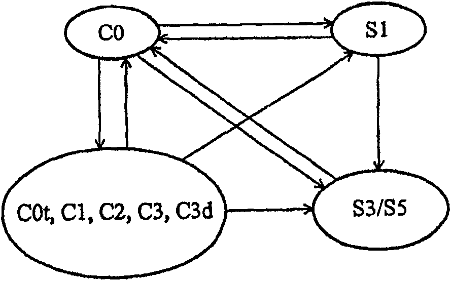
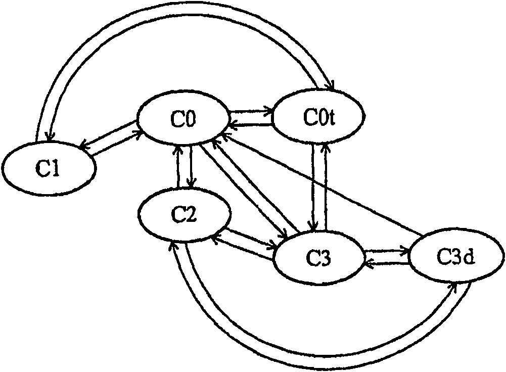
[0030] In the present invention, the north bridge 3 with power state management capability includes: the flow monitor 39 monitors the power state transition of the above-mentioned processor according to the power state control si...


PUM


Abstract

A Northbridge power management device and method. The north bridge monitors the power state change of the processor, and then adjusts the working clock and the working voltage of the processor and the main memory according to the determined power state, so as to save power consumption.

Description

technical field [0001] The present invention relates to a power state management method, and particularly to a northbridge power state management method. Background technique [0002] Power management is an important topic in computer design, especially for mobile computing devices. The long battery life expected by design requires aggressive power management. Some units in a computer system with a high clock frequency, such as a central processing unit (CPU), a random access memory (RAM), and a chipset, generally consume more power than other units. These high clock operating units make power management play a critical role. [0003] The Advanced Configuration and Power Interface (ACPI) specification 2.0 proposes a number of methods to change the power state of a computer device through operating system-directed configuration and power management (OSPM) The system and south bridge can be used to switch the computer device between S0, S1, S2, S3, S4, S5 states, and switch...

Claims


Application Information

Patent Timeline
Patent Type & Authority Patents(China)
IPC IPC(8): G06F1/32
Inventor 林瑞霖赖瑾郭宏益
Owner VIA TECH INC
Features
  • R&D
  • Intellectual Property
  • Life Sciences
  • Materials
  • Tech Scout
  • Unparalleled Data Quality
  • Higher Quality Content
  • 60% Fewer Hallucinations
Learn More