Thin slide unit

A thin, rolling groove technology, which is applied to bearing components, linear motion bearings, bearings, etc., can solve the problems of increased sliding resistance of sliding parts, short life of roll forming dies, and decreased rigidity of guide rails. Effects of small size, reduced manufacturing cost, and reduced frequency of replacement

Active Publication Date: 2009-10-28
THK CO LTD
View PDF4 Cites 0 Cited by
  • Summary
  • Abstract
  • Description
  • Claims
  • Application Information

AI Technical Summary

Problems solved by technology

However, when the guide claw is deformed as described above, since the guide claw contacts the side wall of the relief groove, there is a problem that the sliding resistance of the slider relative to the guide rail increases.
[0011] In addition, the relief groove is formed by roll forming at the same time as the ball rolling groove on the guide rail, but since the width of the relief groove corresponds to the thickness of the guide plate, it is extremely small, so the life of the roll forming die forming the relief groove is shortened. Extremely short, there is a problem that the manufacturing cost increases due to the replacement of the mold
In addition, since a relief groove is formed at the center of the ball rolling groove, the wall thickness of the guide rail becomes thinner at the portion where the relief groove is formed, which is one of the causes of a decrease in the rigidity of the guide rail.
[0012] Furthermore, the ball carriage sandwiches the guide plate between the two ball plates and assembles these plates with rivets. However, as mentioned above, since the tip of the guide claw is sharp, it is necessary to fully consider ensuring that the ball carriage is assembled. operator safety, which also makes operability less

Method used


Image

  • Thin slide unit
  • Thin slide unit
  • Thin slide unit

Examples


Embodiment Construction

[0028] The thin sliding unit of the present invention will be described in detail below with reference to the drawings.

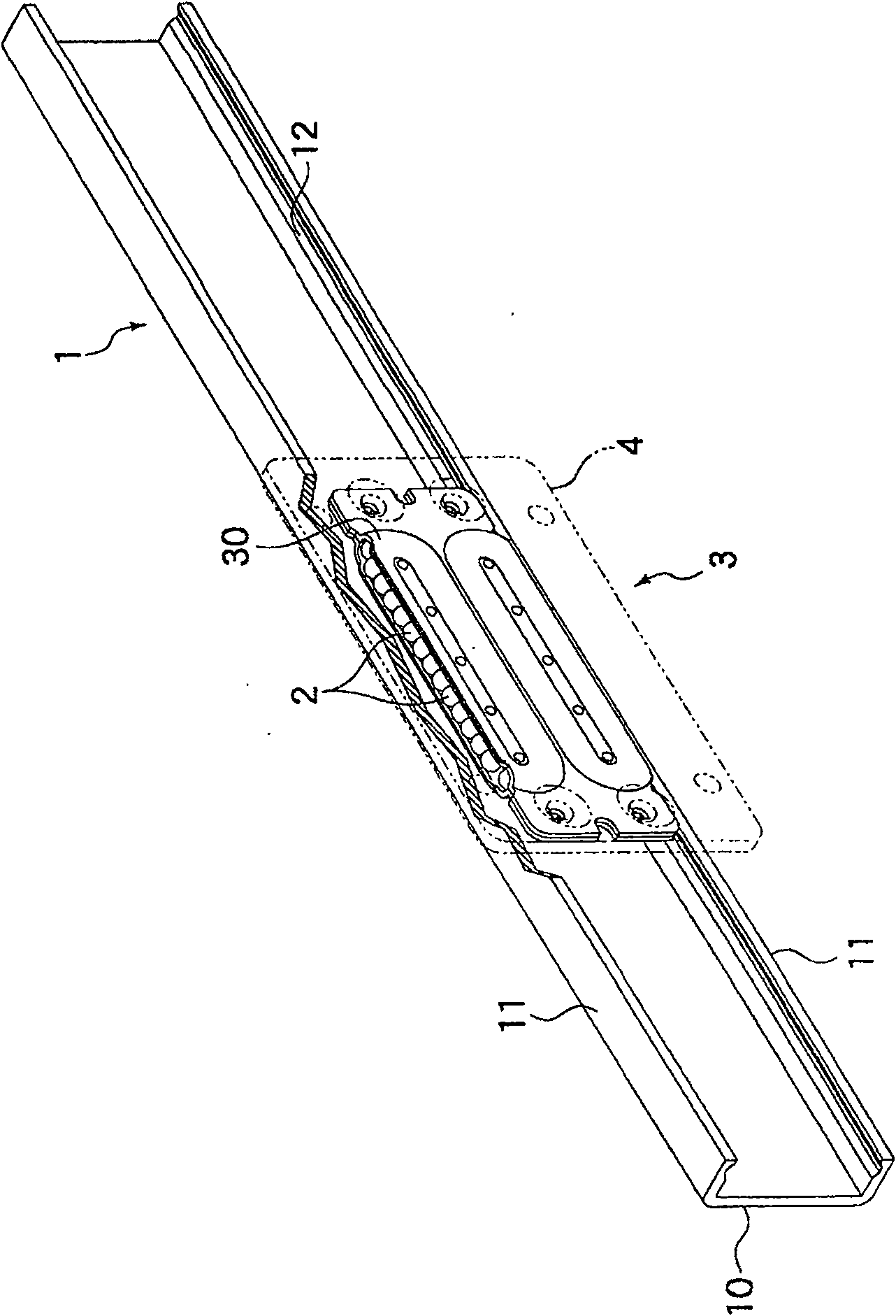
[0029] figure 1 It is a figure which shows an example of the slide unit to which this invention is applied. The sliding unit is composed of a guide rail 1 and a slider 3 assembled on the guide rail 1 via a plurality of balls 2 , and the slider 3 is configured to freely reciprocate along the guide rail 1 .

[0030] The guide rail 1 is formed in a channel shape in which a pair of side walls 11 and 11 stand up from a base 10 , and a space surrounded by the base 10 and the side walls 11 serves as a guide path for the slider 3 . On the inner side of each side wall 11 facing the guide way, a rolling groove 12 of the ball 2 is formed along the longitudinal direction of the guide rail 1, and these rolling grooves 12 face each other via the guide way. Each rolling groove 12 is formed in a so-called Gothic arch shape in which two ball rolling surfaces intersect at...


PUM


Abstract

The present invention provides a thin sliding unit which, when assembling two ball plates with rail-shaped ball grooves to form an infinite circulation path for balls, does not use a guide plate, but only by directly combining the two ball plates can make the balls Smooth circulation can realize the smooth reciprocating movement of the slider relative to the guide rail. The ball infinite circulation path of the slider is formed by abutting two ball plates formed with track-shaped ball grooves and directly connecting the two ball plates. By making the edges of the two ball plates face each other, a The load opening where the balls in the infinite circulation path contact the rolling grooves of the guide rail also forms a lifting portion that lifts the balls from the rolling grooves and guides them into the infinite circulation path.

Description

technical field [0001] The present invention relates to a sliding unit which can move unrestrictedly along the guide rail through a plurality of balls assembled on the guide rail, which is used on a sliding part such as a copy machine, a protective cover of a working machine, and a weight door, and particularly relates to a sliding unit by A thin sliding unit is assembled in which a plurality of press-formed metal plates are applied to form the infinite circulation path of the balls on the sliding member. Background technique [0002] Conventionally, as a linear guide device utilizing the rolling motion of balls, there has been known a device consisting of a guide rail in which rolling grooves of balls are formed in the longitudinal direction, and a guide rail with a plurality of balls mounted on the guide rail and having an infinite loop of the balls. The sliding member of the road is constituted, and the sliding member freely reciprocates along the guide rail while the bal...

Claims


Application Information

Patent Timeline
Patent Type & Authority Patents(China)
IPC IPC(8): F16C29/06F16C33/60
CPCF16C29/0607
Inventor 粕川励齐藤洋宫崎英儿
Owner THK CO LTD
Why Eureka
Try Eureka