Optical speculum orthoptic ultrasonic therapy system
An ultrasonic treatment and optical technology, applied in the field of medical devices, can solve the problems of increasing the pain of patients, reducing the temperature rise of ultrasonic transducers, increasing the diameter, etc., to achieve the effect of reducing pain and ensuring normal operation
- Summary
- Abstract
- Description
- Claims
- Application Information
AI Technical Summary
Problems solved by technology
Method used
Image
Examples
Embodiment 1
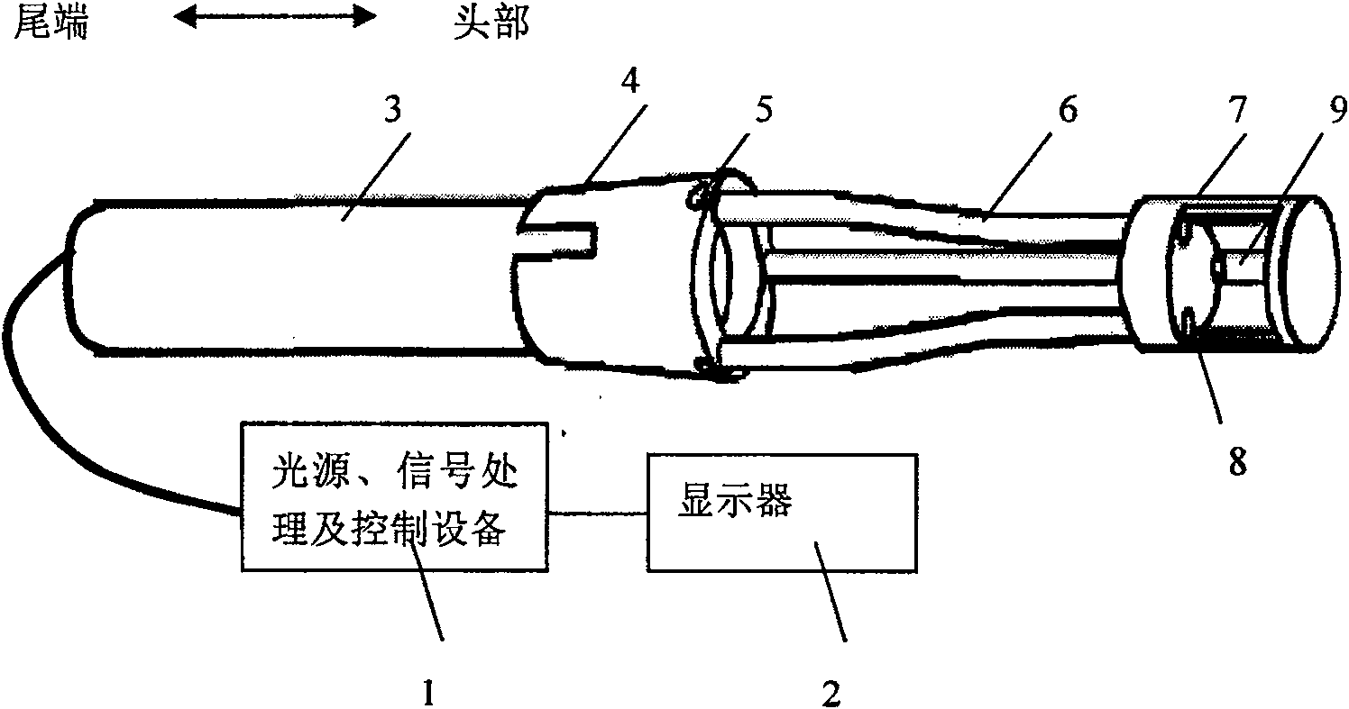
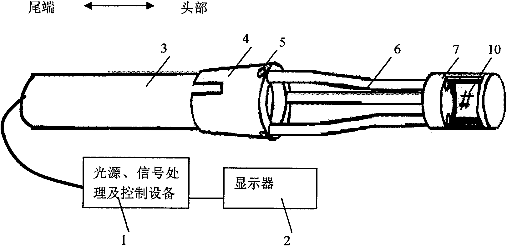
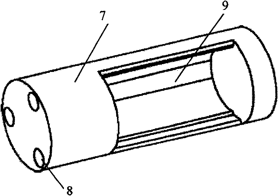
[0036] Such as figure 1 , 2 As shown, the ultrasonic therapeutic system in this embodiment includes an optical speculum, an ultrasonic therapeutic head 7 and a supporting device for fixing the ultrasonic therapeutic head 7 to the front end of the optical speculum head 3 .
[0037] In this embodiment, the light source, signal processing and control device 1 and display 2 of the optical scope are the inherent equipment of the optical scope in the prior art, and no detailed description is required.
[0038] The front end of the optical scope head 3 is connected to the supporting device through a joint 4. In order to ensure a tight connection, in this embodiment, the joint 4 adopts an elastic joint, and its three-dimensional structure is as follows: Figure 4 As shown, the hole 5 on the joint 4 is a channel for installing conductive wires and pouring fluid into the ultrasonic therapy head 7 . The fluid is degassed water.
[0039] The ultrasonic therapy head 7 includes an ultras...
Embodiment 2
[0046] Such as Figure 5 As shown, in the present embodiment, the end portion of the ultrasonic treatment head 7 has a window 15 for the ultrasonic transducer to emit ultrasound, and the ultrasonic transducer 10 is placed in it, and the ultrasonic transducer 10 is placed at the end of the ultrasonic treatment head 7. The targeted area is treated in a focused manner. In order to prevent the outflow of degassed water inside the ultrasonic treatment head 7, at the window 15 at the end of the ultrasonic treatment head 7, the entire ultrasonic treatment head 7 is sealed through a sound-permeable membrane (not shown in the figure).
[0047] The difference between this embodiment and Embodiment 1 is that the position of the ultrasonic transducer 10 is at the end of the ultrasonic treatment head 7, and the ultrasonic treatment head 7 with a window 15 at the end is mainly used to treat diseases at the bottom or roots, etc. Such as the treatment of cervicitis, chronic pharyngitis and s...
Embodiment 3
[0050] Such as Figure 6 As shown, the supporting device in this embodiment is an integral hollow sleeve 11 processed from transparent materials.
[0051] The shape of the hollow sleeve 11 can adopt a straight tube type or a variable radius curved tube structure according to the specific part to be treated. In this embodiment, the diameter of the casing decreases step by step. Such as Figure 7 As shown, the hollow casing 11 is divided into three sections, namely, the front section 12 of the casing, the middle section 13 of the casing, and the rear section 14 of the casing. There are ultrasound therapy heads7. The inner diameter of the front section 12 of the sleeve tube is slightly smaller than the outer diameter of the optical scope head 3, so that when the front end of the optical scope head 3 is inserted into the hollow sleeve 11, the whole ultrasonic treatment head 7 can be connected with the optical scope head 3 as a whole . The middle section 13 of the casing is th...
PUM
 Abstract
Description
Claims
Application Information
 - R&D
- Intellectual Property
- Life Sciences
- Materials
- Tech Scout
- Unparalleled Data Quality
- Higher Quality Content
- 60% Fewer Hallucinations
Browse by: Latest US Patents, China's latest patents, Technical Efficacy Thesaurus, Application Domain, Technology Topic, Popular Technical Reports.
© 2025 PatSnap. All rights reserved.Legal|Privacy policy|Modern Slavery Act Transparency Statement|Sitemap|About US| Contact US: help@patsnap.com


