Maching station, maching device and method of positioning workpiece on the maching unit

A technology of processing unit and processing equipment, applied in metal processing equipment, metal processing mechanical parts, metal processing and other directions, can solve the problems of high cost, unsuitable to achieve high efficiency, etc., to achieve cost reduction, high suitability and flexibility, Pause reduction effect

Inactive Publication Date: 2009-11-25
GROB WERKE & K G
View PDF5 Cites 0 Cited by
  • Summary
  • Abstract
  • Description
  • Claims
  • Application Information

AI Technical Summary

Problems solved by technology

[0007] In addition to this high expense, this device is also unsuitable for high efficiency, because the workpiece support must be removed from the machining center, that is, from the vicinity of the machining spindle, in order to remove the processed workpieces and accommodate new ones at a remote workpiece change position. the workpiece

Method used


Image

  • Maching station, maching device and method of positioning workpiece on the maching unit
  • Maching station, maching device and method of positioning workpiece on the maching unit
  • Maching station, maching device and method of positioning workpiece on the maching unit

Examples


Embodiment Construction

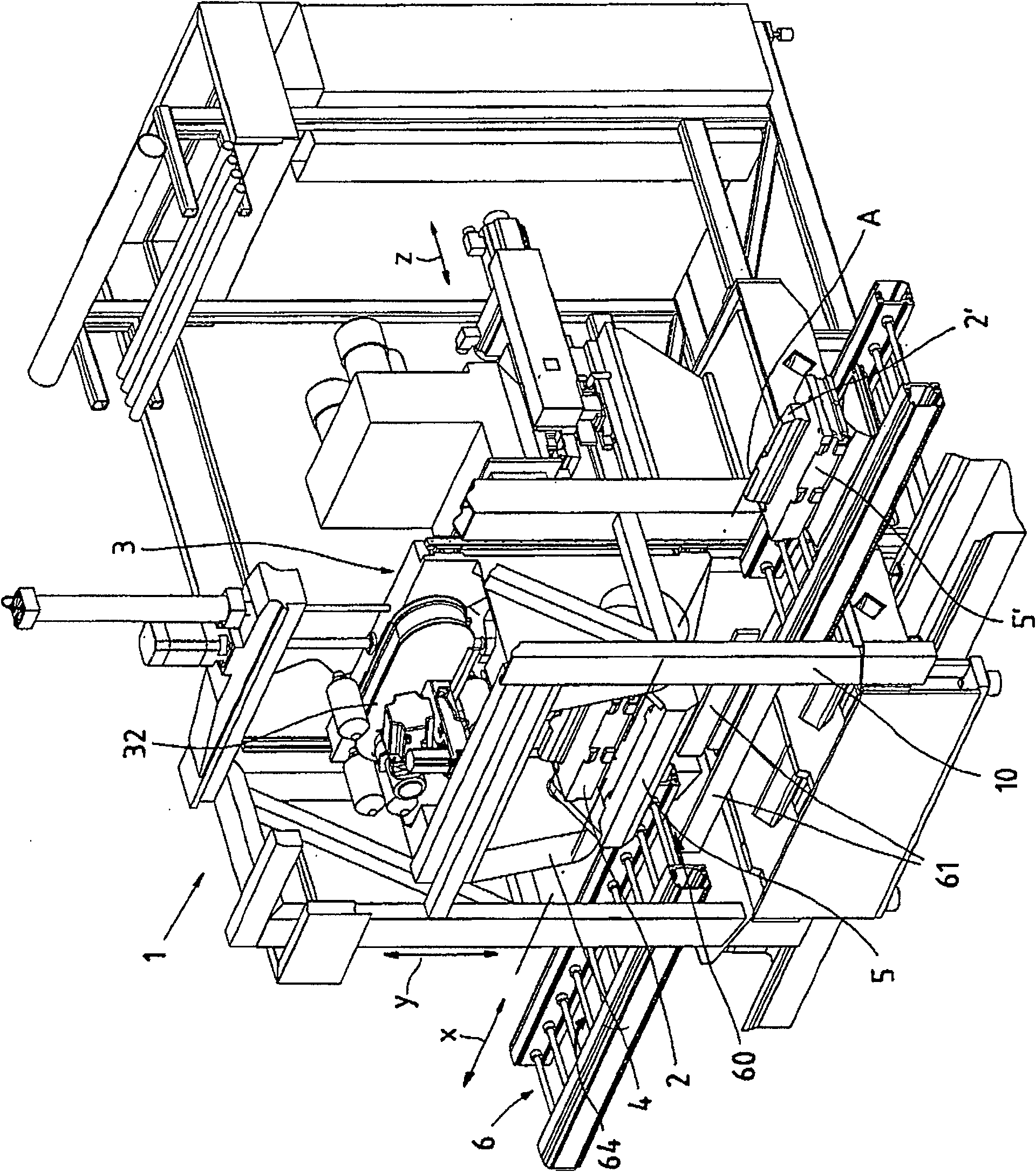
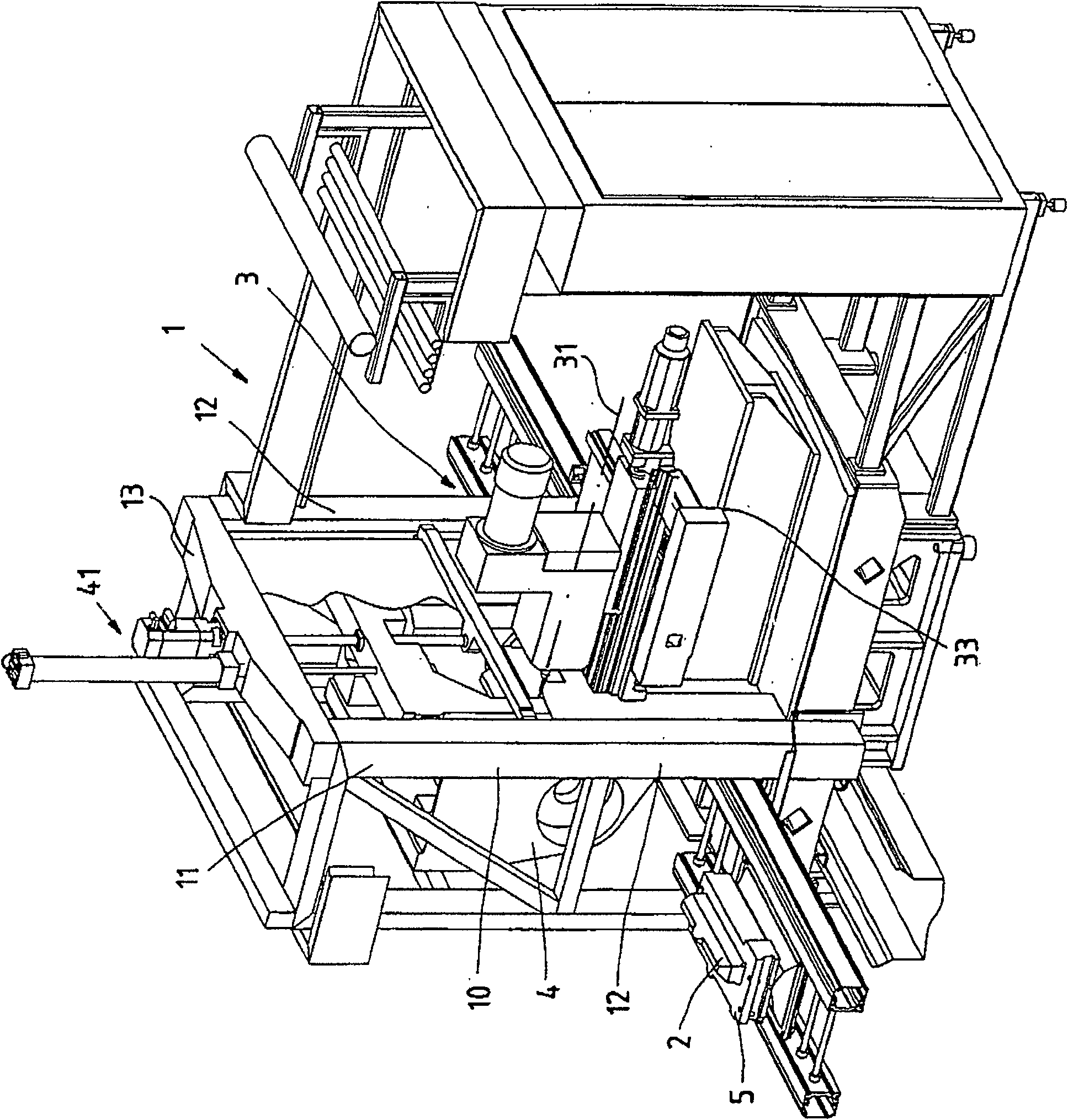
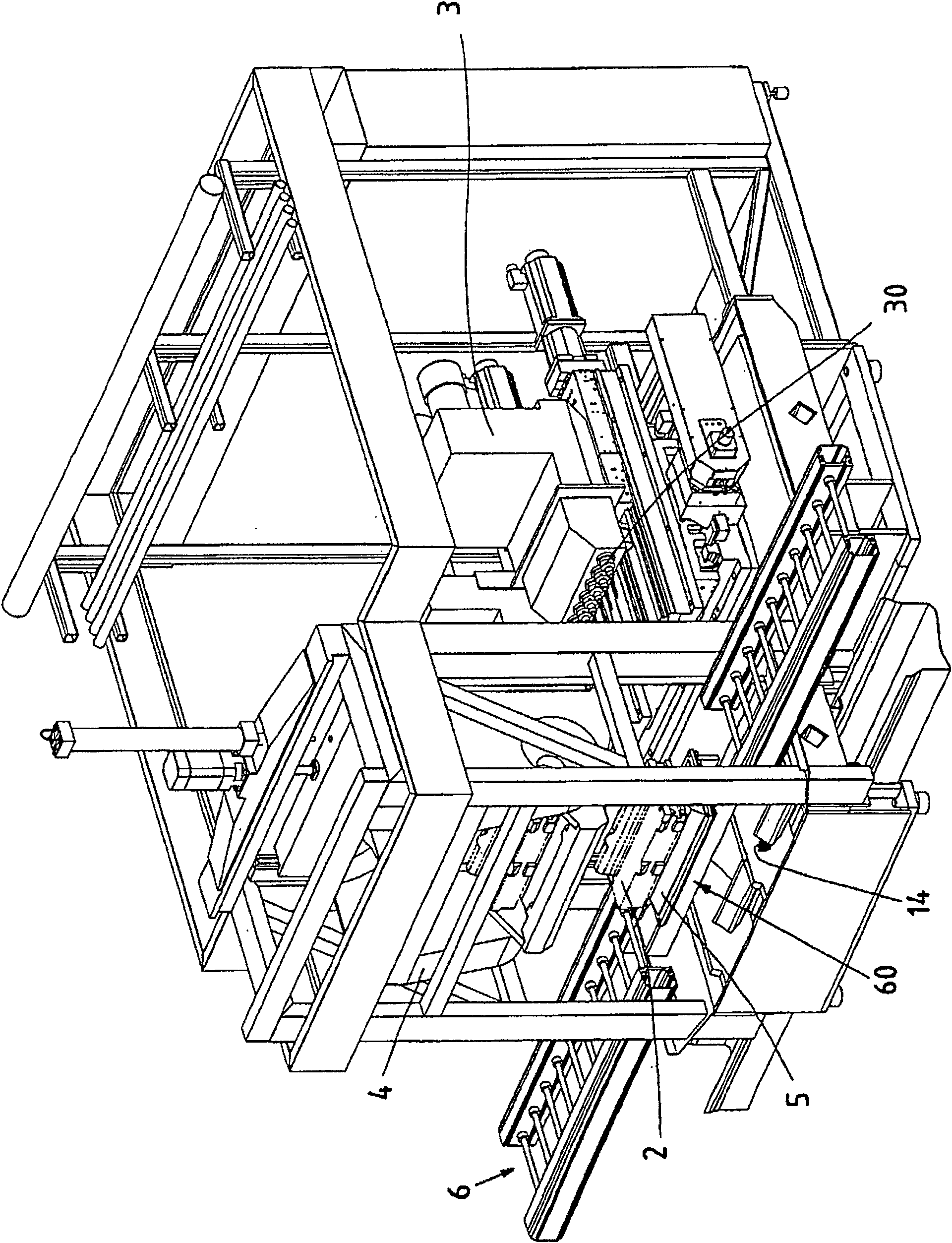
[0100] A processing station 1 according to the invention is shown, for example, in figure 1 middle. The machining station basically comprises a machining unit 3 for machining workpieces 2 . The machining unit 3 has a mobility along the Z axis, which is parallel to the spindle axis and, if necessary, also perpendicular thereto along the X axis. wherein the Z-axis and the X-axis are oriented horizontally or substantially horizontally. The vertical axis (Y axis) is provided by the workpiece slide 4 carrying the workpiece 2 , in particular during or for machining.

[0101] The processing station according to the invention is often part of a processing plant which is also according to the invention, for example a conveyor line. A plurality of processing stations arranged in succession are connected to one another by means of a conveyor track 6 . The area of ​​the transport track 6 where the workpieces 2 are fed is marked here with 64 . figure 1 The situation is shown in which ...


PUM


Abstract

The machining point (1) has at least one machining unit (3) to machine workpieces (2). The workpiece is transported to a transfer point (60) where it is picked up by a workpiece carriage (4), which takes the workpiece to a machining unit and through it along one linear axis.

Description

technical field [0001] The invention relates to a processing station. The invention also relates to a processing device and a method for positioning a workpiece on a processing unit. Background technique [0002] The above-mentioned processing stations are incorporated, for example, in transfer automatic lines. Numerous and often complex processes are performed on workpieces in transfer lines. For this purpose, a number of processing stations are provided in succession. Especially for machining and are connected to each other by conveyor rails. A small number of processing procedures are realized by the processing stations, but many connected processing stations can realize various and complicated processing of the workpiece. [0003] The problem here is of course the high-precision positioning of the workpiece relative to the machining unit or cutting head or tool spindle. [0004] So-called converters or an overhead conveyor are known from the prior art, which remove ...

Claims


Application Information

Patent Timeline
Patent Type & Authority Patents(China)
IPC IPC(8): B23Q7/00B23Q7/14B23Q7/16B23Q39/02B23Q1/48B23Q1/52B23Q1/62B23Q41/04
CPCB23Q41/04B23Q1/621B23Q2039/006B23Q1/4876B23Q7/1426B23Q39/026B23Q1/4857B23Q39/02B23Q1/52Y10T409/306048Y10T29/5124Y10T483/179Y10T29/5196Y10T483/1733
Inventor 布克哈特·格鲁博
Owner GROB WERKE & K G
Why Eureka
Try Eureka