
Combined fly wheel loading unit capable of reconstructing

A loading device, combined technology, applied in the direction of measuring device, testing of machine/structural components, force/torque/work measuring instrument, etc., can solve the requirements that it is difficult to meet the requirements of brake test standards, and the simulation of the actual driving state of the vehicle is not enough. , the flywheel assembly and disassembly process is complicated and other problems, to achieve the effect of precise adjustment, easy operation, accurate disassembly and assembly

Inactive Publication Date: 2009-11-25
ANHUI JEE AUTOMATION EQUIP CO LTD
View PDF5 Cites 0 Cited by
  • Summary
  • Abstract
  • Description
  • Claims
  • Application Information

AI Technical Summary

Problems solved by technology

However, this fixed structure can only be tested for the specific inertia of a specific vehicle in actual use, and the simulation of the actual driving state of the vehicle is far from enough, and it is difficult to meet the requirements of the national standard for brake test standards
At the same time, this structural form makes the assembly and disassembly process of the flywheel complicated and difficult to replace

Method used


Image

  • Combined fly wheel loading unit capable of reconstructing
  • Combined fly wheel loading unit capable of reconstructing

Examples


Embodiment Construction

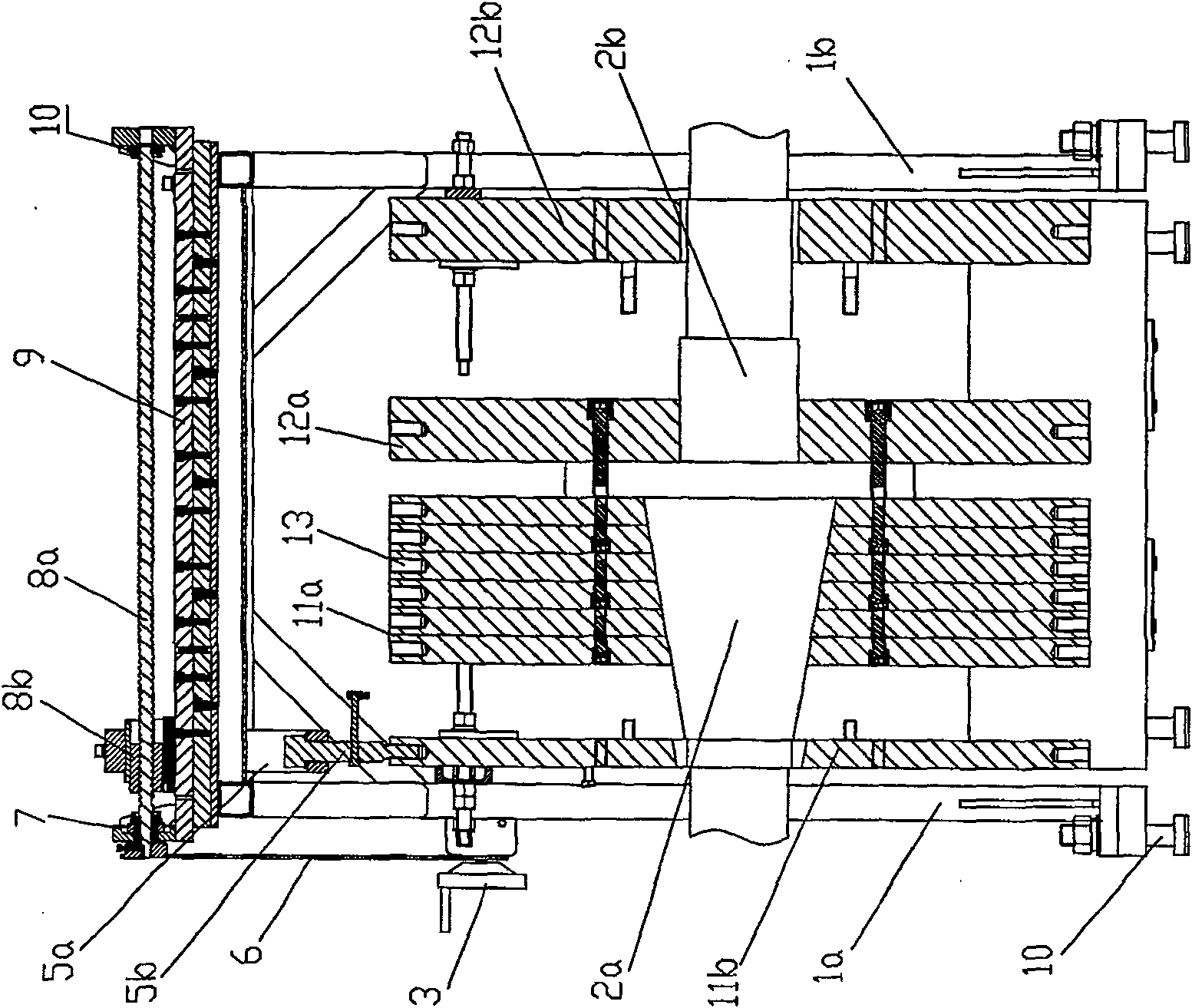
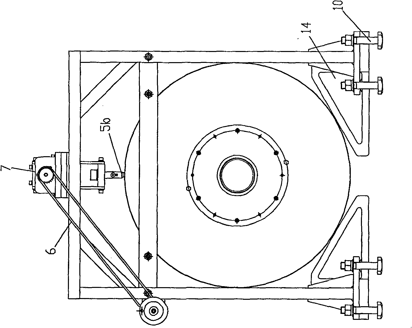
[0022] Referring to the accompanying drawings, in this embodiment, a portal frame consisting of a left side frame 1a, a right side frame 1b and a horizontal top frame is provided. In the portal frame, a plurality of flywheel pieces constitute a flywheel group, and each flywheel piece Set in a series on the rotating shaft in sequence, fixedly set the connecting plate on the rotating shaft, the flywheels for use are sequentially fixed on the connecting plate through the inner hexagonal screws, the idle flywheels are separated from the connecting plate, and are attached to the door frame in sequence The side frame of the side frame, the rotating shaft at the position of the idle flywheel is smaller in diameter than the rotating shaft at the position of the flywheel, and the idle flywheel is supported on the "V" bracket 14 at the bottom of the frame ( figure 2 shown).

[0023] The rotating shaft is centered on the connection plate. The flywheel on the right side of the connection...


PUM


Abstract

The utility model relates to a reconfigurable combined type flywheel loading device, which is characterized in that a gate type stander which comprises side frames of both sides and a horizontal upper-frame is arranged. In the gate type stander a flywheel group comprises several flywheel sheets which bunchily cover a rotating shaft in sequence. A terminal pad is fixedly arranged on the rotating shaft. The cast flywheel sheet is fixed on the terminal pad in sequence by bolts. The idle flywheel sheet is separated from the terminal pad and reclines on the side frame of the gate type stander in sequence. The rotating shaft on the location where the idle flywheel sheet is arranged has a smaller diameter than that on the location where the cast flywheel sheet is arranged. The idle flywheel sheet is supported on a V-shaped bracket on the base of the stander. The utility model is easy to arrange, disassemble and adjust, so the utility model can provide different loading inertia according to different car models and car conditions on the comprehensive performance test bed of an automotive brake and meet the demand of rotary movement accuracy in test modes.

Description

technical field [0001] The present invention relates to auto parts testing equipment, more specifically a loading device on a test bench for the braking performance of an automobile brake, which converts the translational inertia of the vehicle into the rotational inertia, and simulates the actual braking of the vehicle through the loading device the braking process. Background technique [0002] The car brake is the main component of the car braking system, which enables the car to stop in a short distance while maintaining the stability of the driving direction, keeps the speed of the car running downhill stable, and keeps the stopped car still. The quality of its performance directly affects the safety performance of the vehicle, and the braking performance of the vehicle is an important guarantee for the safe driving of the vehicle. Improving the braking performance of automobiles is always an important task of the automobile design, manufacture and use departments. Co...

Claims


Application Information

Patent Timeline
Patent Type & Authority Patents(China)
IPC IPC(8): G01M17/007G01L5/28B60T17/22
Inventor 林巨广谢峰杨丽英赵刚刘波
Owner ANHUI JEE AUTOMATION EQUIP CO LTD
Learn More